TL494 Current-Mode PWM Controller
The TL494 IC is a fixed frequency current-mode PWM controller IC with all the functions that are required in the construction of the pulse-width modulation (PWM) control circuit on a single chip.
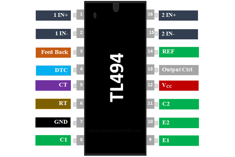
TL3843 Pinout Configuration
|
Pin Number |
Pin Name |
Description |
|
1 |
1IN+ |
Noninverting input to error amplifier 1 |
|
2 |
1IN- |
Inverting input to error amplifier 1 |
|
3 |
FEEDBACK |
Input pin for feedback |
|
4 |
DTC |
Dead-time control comparator input |
|
5 |
CT |
Capacitor terminal used to set the oscillator frequency |
|
6 |
RT |
Resistor terminal used to set the oscillator frequency |
|
7 |
GND |
Ground Pin |
|
8 |
C1 |
The collector terminal of BJT output 1 |
|
9 |
E1 |
The emitter terminal of BJT output 1 |
|
10 |
E2 |
The emitter terminal of BJT output 2 |
|
11 |
C2 |
The collector terminal of BJT output 2 |
|
12 |
VCC |
Positive Supply |
|
13 |
OUTPUT CTRL |
Selects single-ended/parallel output or push-pull operation |
|
14 |
REF |
The 5-V reference regulator output |
|
15 |
2IN- |
Inverting input to error amplifier 2 |
|
16 |
2IN+ |
Noninverting input to error amplifier 2 |
TL494 Specifications & Features
- Supply Voltage: 7V to 40V
- Number of Outputs: 2 Output
- Switching Frequency: 300 kHz
- Duty Cycle - Max: 45 %
- Output Voltage: 40 V
- Output Current: 200 mA
- Fall Time: 40 ns
- Rise Time: 100 ns
- Available in 16-pin PDIP, TSSOP, SOIC and SOP Packages
Note: Complete Technical Details can be found in the TL494 datasheet given at the end of this page.
Equivalent/Substitute for TL494: UC3843, TL3842
Alternatives PWM controller IC: UC2842, SG2524
Where to use the TL494 PWM Controller IC
The TL494 fixed frequency PWM Controller can be used for DC to DC conversion regardless of buck or boost topology. TL494 can be used to provide a constant current by varying the output voltage to the load. This IC feature an output control circuit, a flip flop, a dead time comparator, two different error amplifiers, a 5V reference voltage, an oscillator, and a PWM comparator.
So if you are looking for an IC to produce PWM signals for controlling a power switch based on the current flowing through the circuit, then this IC might be the right choice for you.
How to use TL494 IC
A test circuit from the TL494 datasheet is shown below.
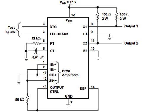
Non inverting pins are connected to the Ref pin while inverting pins are connected to the ground. Test inputs are given to DTC and FEEDBACK pins. External capacitor and resistor are connected to pin 5 & 6 to control the oscillator frequency. The error amplifier compares a sample of the 5-V output to the reference and adjusts the PWM to maintain a constant output current
Applications of TL494
- Desktop PCs
- Microwave Ovens
- Server PSUs
- Solar Micro-Inverters
- Washing Machines: Low-End and High-End
- E-Bikes
- Power: Telecom/Server AC/DC Supplies:
- Smoke Detectors
- Solar Power Inverters
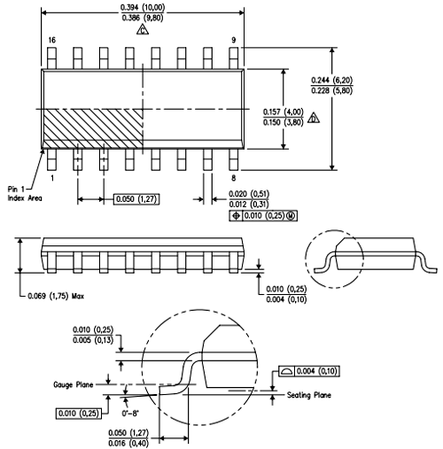
2D-Model of TL494
Dimensions for TL3494 IC is given below. These dimensions are for the PDSO package. If you are using a different package IC, please refer to the TL494 datasheet.