MCP2200 - USB 2.0 to UART Protocol Converter with GPIO
The MCP2200 is a USB -to-UART serial converter chip developed by Microchip Technology. We can use MCP2200 to convert a USB connection to a serial interface. It supports 12mb/s speed and can send and receive 64 bytes. Unlike other USB to UART converters, MCP2200 has 8 general purpose I/O pins. Four of the pins have alternate functions to indicate USB and communication status. Only a few components are needed for the proper working of this IC. The integrated termination resistors in the MCP2200 make it a more convenient and cost-effective solution for adding USB connectivity to your UART-based devices. The MCP2200 also has 256 bytes of integrated user EEPROM. This IC is available in 20-lead VQFN (5x5 mm), 20-lead SOIC and 20-lead SSOP packages.
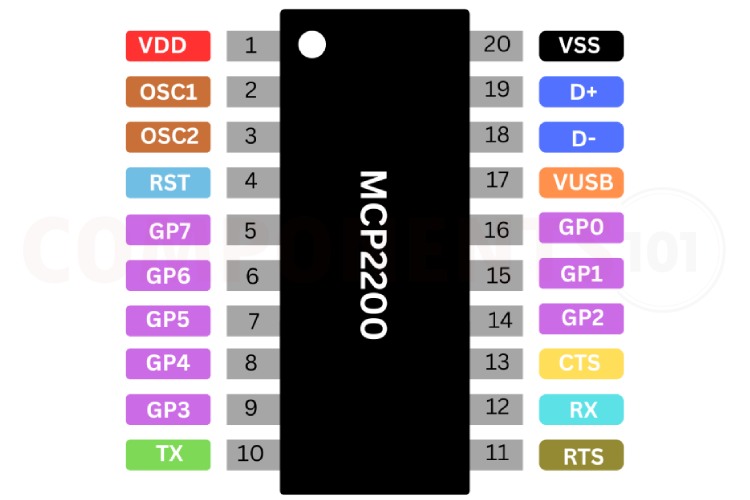
MCP2200 Pinout Configuration
Here are the pinout details for MCP2200.
| Pin Name | VQFN | SSOP, SOIC | Pin Type | Standard Function |
| GP0/SSPND | 13 | 16 | I/O | General purpose I/O |
| GP1/USB- CFG | 12 | 15 | I/O | General purpose I/O |
| GP2 | 11 | 14 | I/O | General purpose I/O |
| GP3 | 6 | 9 | I/O | General purpose I/O |
| GP4 | 5 | 8 | I/O | General purpose I/O |
| GP5 | 4 | 7 | I/O | General purpose I/O |
| GP6/RxLED | 3 | 6 | I/O | General purpose I/O |
| GP7/TxLED | 2 | 5 | I/O | General purpose I/O |
| CTS | 10 | 3 | I | Hardware flow control “Clear to Send” input signal |
| RTS | 8 | 11 | O | Hardware flow control “Request to Send” output signal |
| Rx | 9 | 12 | I | USART RX input |
| Tx | 7 | 10 | O | USART TX output |
RST |
1 | 4 | I | Reset input must be externally biased |
| VDD | 18 | 1 | P | Power |
| VSS | 17 | 20 | P | Ground |
| OSC1 | 19 | 2 | I | Oscillator input |
| OSC2 | 20 | 3 | O | Oscillator output |
| D+ | 16 | 19 | I/O | USB D+ |
| D- | 15 | 18 | I/O | USB D- |
| Vusb | 14 | 14 | P | USB power pin (internally connected to 3.3V). Should be locally bypassed with a high-quality ceramic capacitor. |
| EP | 21 | - | - | Exposed Thermal Pad (EP). Do not electrically connect. |
Features of MCP2200
MCP2200 USB to Serial converter has the following key features:
- Supports Full-Speed USB (12 Mb/s)
- Class 02h - CDC: USB-to-UART communications and I/O control
- Class 03h - HID: I/O control, EEPROM access, and initial configuration
- 64 byte transmit
- 64 byte receive
- Fully configurable VID and PID assignments, and string descriptors
- Bus Powered or self powered USB Driver and Software Support
- Windows XP(SP2 and later)/Vista/7
- Configuration utility for initial configuration
- Support baud rates: 300 - 1000k (baud)
- Hardware flow control
- UART signal polarity option General Purpose Input/Output (GPIO) Pins
- Eight (8) general purpose I/O pins
- 256 bytes of user EEPROM
- USB activity LED outputs (TxLED and RxLED)
- SSPND output pin
- ULOAD output pin (indicates if requested current was allowed)
- Operating voltage: 3.0 - 5.5 (V)
- Oscillator input: 12 MHz
- ESD protection > 4kV HBM
- Industrial (I) Operating Temperature: -40°C to +85°C
Manufacturers of MCP2200:
The MCP2200 is manufactured by Microchip Technologies. There are no alternative manufacturers for the same part number as of the date of writing this article.
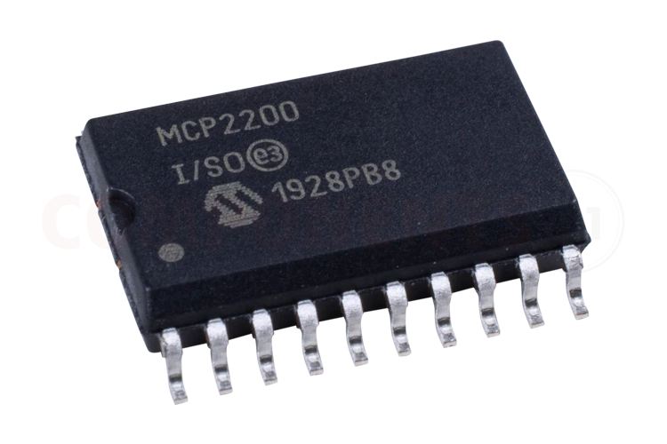
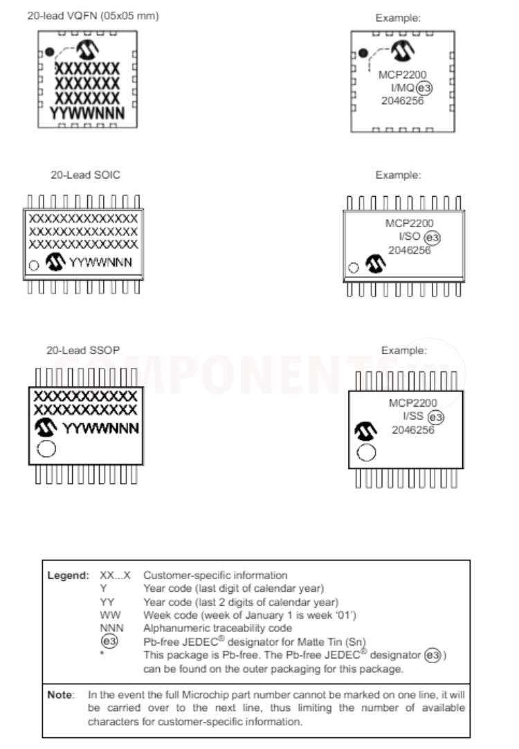
MCP2200 Variants and Identification
The MCP 2200 comes in 3 different packages VQFN, SOIC and SSOP. MCP2200- I/MQ and MCP2200T- I/MQ come in 20Pin QFN package, while MCP2200- I/SO and MCP2200T- I/SO come in SOIC package and MCP2200- I/SS and MCP2200T- I/SS come in SSOP packages.
MCP2200 Equivalents
If you are looking for an equivalent or replacement for MCP2200, we weren’t able to find any other chip that is pin-to-pin compatible.
MCP2200 Alternatives
If you are looking for an alternative for MCP2200 you can look at the other IC from these.
CH340, MA112AS16, FT230x, CP2102, PL2303HX, CH9102, CH343, CH341, CP2110, FT232
Note: Complete technical details can be found in the MCP2200 datasheet at this page’s end.
MCP2200 Schematics
The following image shows the typical circuit diagram for MCP2200.
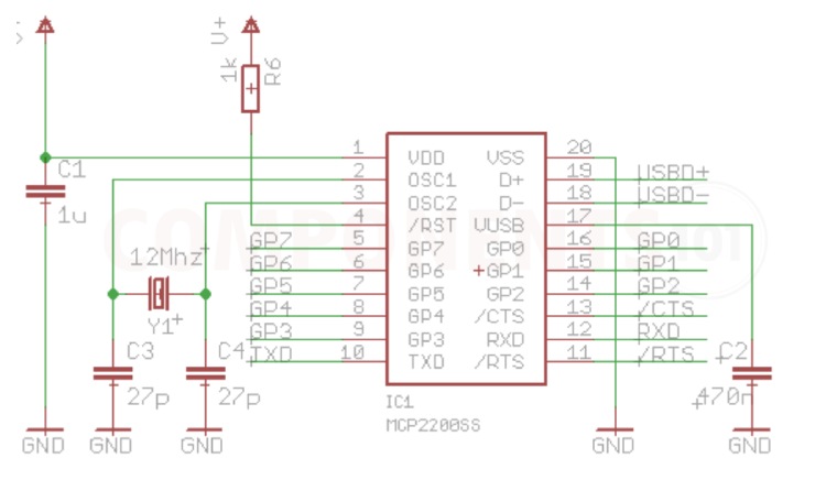
This circuit shows the basic configuration of the MCP2200 IC as you can see, we can connect the D+ and D- pins of the IC directly to the USB data pins. The capacitors connected across the power supply is to stabilise the voltage and reduce the noise. the reset pin is held high for normal operation with a 1K pull-up resistor (R6) and an internal 3.3volt regulator supplies the USB peripheral, it requires an external 470nF capacitor (C2). Here we used a 12Mhz crystal(Y1) and two 27pF capacitors (C3, C4) to provide the clock signal to MCP2200. This is necessary to provide a stable clock pulse to MCP2200 for proper working. We can connect the Tx and Rx lines of MCP2200 to any microcontroller or similar circuits. Remember to connect the Tx to the Rx of the receiver and the Rx to the Tx of the receiver.
Problems with using MCP2200?
I made a USB-to-serial converter using MCP2200 but I am unable to communicate?
It's due to several reasons but you can check these:
- Double-check all connections between the MCP2200 chip and the other components of your circuit. Make sure that the TX and RX lines are connected correctly to the devices you are trying to communicate with.
- Check that the voltage levels of the signals (TX, RX, etc.) are compatible with the devices you are connecting to.
- Sometimes, the issue could be with the USB cable itself. Try using a different USB cable to see if that resolves the problem.
- Make sure you have selected the correct baud rate and other settings.
How can I test if my MCP2200 is working properly?
Make sure that the serial settings (baud rate) on your computer match those of the device you are trying to communicate with. Try connecting the TX and RX pins of the MCP2200 together (a loopback test). Send some data from your computer, and if it's received correctly, it indicates that the MCP2200 is working.
My computer is not recognizing the MCP2200 circuit.
- Make sure that you have the correct drivers installed for the MCP2200 chip on your computer. The drivers are necessary for the computer to recognize and communicate with the chip.
- In Windows, check the Device Manager to see if the MCP2200 is recognized correctly without any error messages. If there are errors, it could indicate a driver issue or a problem with the hardware connection.
Design choices to be considered with MCP2200
What are the design considerations when designing a PCB using MCP2200?
- Place the USB port near the MCP2200 IC, and the data lines track should route straight forward. The D+ and D- signal lines are placed close to the parallel wiring, and ground or copper should be provided on both sides to reduce signal interference from the other parts.
- Minimize the via count in data lines.
- Should use filter capacitors and also keep all components tightly.
Applications of MCP2200
- Microcontroller Programming
- Debugging and Testing
- Industrial Control Systems
- DIY Electronics Projects
- Legacy Device Support
- Automation and Robotics
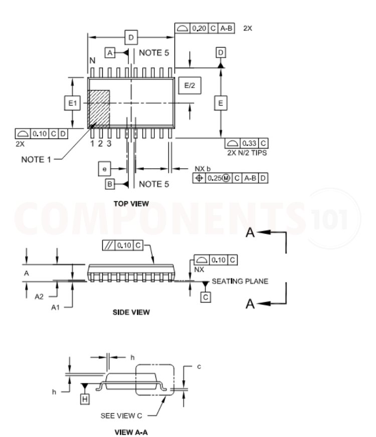
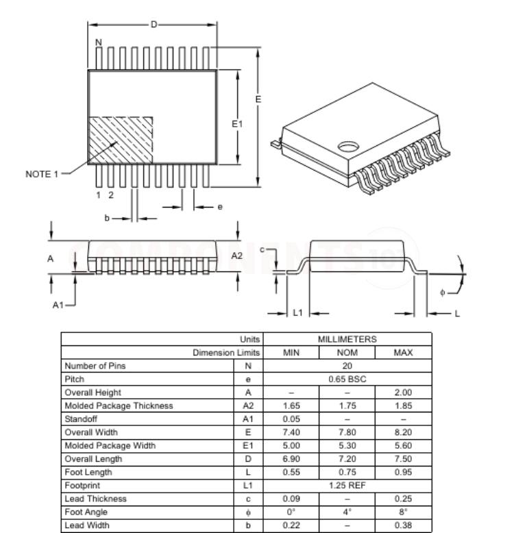
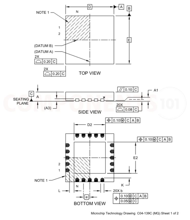
Footprint information and dimensions of MCP2200
Here you can find the mechanical drawings of MCP2200 along with its dimensions. The dimensions can be used to create custom footprints of the IC and be used for PCB or CAD modelling.