CH9102 High-Speed USB to Serial Chip
The CH9102 is a stable, reliable single-chip USB to serial UART converter designed by WCH (Nanjing QinHeng Corp). It is commonly used in USB-to-serial adapter cables and development boards. It has an inbuilt crystal oscillator and power-on reset function. The chip provides a convenient way to add USB connectivity to microcontroller-based projects, allowing them to communicate with a computer. It requires only minimal external components to work. CH9102 can be used to migrate legacy serial port-based devices to USB. This IC offers X-On/X-Off handshaking, Line break transmission, Asynchronous serial data transfer etc. The CH9102 is available in QFN24 and QFN28 lead-free packages.
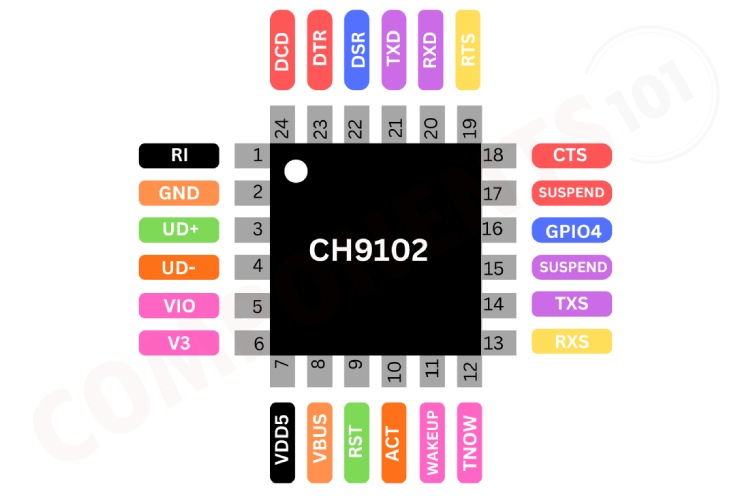
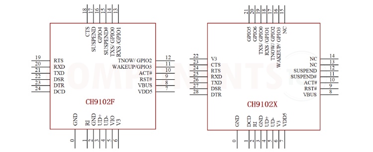
CH9102 Pinout Configuration
Here are the pinout details for CH9102 in QFN24 package. The CH9102 is also available in QFN28 package. For its pinout, please check the
| QNF24 Pin No |
QNF28 Pin No |
Pin Name | Pin Type | Pin Description |
| 7 | 7 | VDD5 | POWER | Power supply voltage input, requires an external decoupling capacitor |
| 5 | V3 connected to VIO internally |
VIO | POWER | I/O power supply voltage input, requires an external decoupling capacitor |
| 2,0 | 3, 0 | GND | POWER | Ground, connected to ground of USB bus directly |
| 6 | 6,22 | V3 | POWER | Internal voltage regulator output and kernel and USB power supply input. When VDD5 voltage is less than 3.6V, connects to VDD5. When VDD5 voltage is more than 3.6V, connects to external 0.1uF decoupling capacitor |
| 9 | 9 | RST | IN | Input of external reset, active low, built-in pull-up resistor |
| 3 | 4 | UD+ | USB signal |
Connect to USB D+ Signal directly, do not series resistors |
| 4 | 5 | UD- | USB signal |
Connect to USB D- Signal directly, do not series resistors |
| 8 | 8 | VBUS | IN | VBUS status detection input of USB bus, built-in pull-down resistor |
| 21 | 26 | TXD | OUT | Transmit asynchronous data output, idle state is high level |
| 20 | 25 | RXD | IN | Receive asynchronous data input, integrated pull-up resistor |
| 18 | 23 | CTS | IN | MODEM input signal, clear to send, active low |
| 22 | 27 | DSR | IN | MODEM input signal, data set ready, active low |
| 1 | 2 | RI | IN | MODEM input signal, ring indicator, active low |
| 24 | 1 | DCD | IN | MODEM input signal, data carrier detect, active low |
| 23 | 28 | DTR | OUT | MODEM output signal, data terminal ready, active low |
| 19 | 24 | RTS | OUT | MODEM output signal, request to send, active low |
| 15 | 11 | SUSPEND# | OUT | USB suspend state output, active low, normal working state output high level, output low level after suspension |
| 17 | 12 | SUSPEND | OUT | USB suspend state output, active high, normal working state output low level, output high level after suspension |
| 11 | 16 | WAKEUP/ GPIO3 | IN/ (IN/OUT) | USB wake-up event detects input, low active, built-in pull-up resistor General GPIO3, input or output controlled by driver software t |
| 12 | 17 | TNOW/ GPIO2 | OUT/ (IN/OUT) | The serial port sends the status indication in progress, active high General GPIO2, input or output controlled by driver software |
| 13 | 18 | RXS/GPIO1 | OUT/ (IN/OUT) | RXD pin receives status output; General GPIO1, input or output controlled by driver software |
| 14 | 19 | TXS/GPIO0 | OUT/ (IN/OUT) | TXD pin transmits status output; General GPIO0, input or output controlled by driver software |
| NONE | 20 | GPIO6 | IN/OUT | General GPIO6, input or output controlled by driver software |
| NONE | 21 | GPIO5 | IN/OUT | General GPIO5, input or output controlled by driver software |
| 16 | NONE | GPIO4 | IN/OUT | General GPIO4, input or output controlled by driver software |
| 10 | 10 | ACT# | OUTPUT | USB configuration completed state output, active low, invalid when suspended |
| NONE | NC | 13, 14, 15 | NONE | No Connection must be suspended |
Features of CH9102
CH9102 USB to Serial converter has the following key features:
- Full-speed USB device interface, USB 2.0 compatibility.
- Built-in firmware emulates the standard UART interface, used to upgrade the original serial peripherals
- expand additional UART via USB.
- Original serial applications are totally compatible without any modification in Windows operating systems.
- supports built-in CDC driver or multi-functional high-speed VCP vendor driver.
- Hardware full duplex UART interface, integrated independent transmit-receive buffer, supports communication baud rate varies from 50bps to 4Mbps.
- UART supports 5, 6, 7 or 8 data bits, and supports odd, even, space, mark and none parity.
- Supports common MODEM interface signals RTS, DTR, DCD, RI, DSR and CTS.
- Supports CTS and RTS hardware automatic flow control.
- Supports half-duplex, provides sending status TNOW, used for controlling RS485 to transmit-receive switch.
- Supports RS232 interface, through external voltage conversion chip.
- Supports 5V and 3.3V power supply.
- CH9102F UART interface I/O powered independently, support 5V, 3.3V, 2.5V, 1.8V power supply voltages. CH9102X UART interface I/O only supports 3.3V power supply voltage.
- Integrated power-on reset, integrated clock, no external crystal required.
- Built-in EEPROM used to configure the chip of VID, PID, maximum current value, vendor and product information string, etc.
- l Integrated Unique ID (USB Serial Number).
Manufacturers of CH9102:
The CH9102 is manufactured by WCH.cn There are no alternative manufacturers for the same part number as of the date of writing this article.
CH9102 Variants
The CH9102 comes in 2 different packages QFN24 and QFN28.
.
| Package | Body size | Lead pitch | Lead pitch | Description | Part No |
| QF24_4X4 | 4*4mm | 0.5mm | 19.7mil | Square leadless 24-pin patch | CH9102F |
| QF28_5X5 | 5*5mm | 0.5mm | 19.7mil | Square leadless 28-pin patch | CH9102X |
CH9102 Equivalents
If you are looking for an equivalent or replacement for CH9102, you can check out CP2102 or CP2104, both are drop-in replacements for the CH9102.
CH9102 Alternatives
If you are looking for an alternative for CH9102 you can look at the other ICs from these.
CH340, MA112AS16, FT230x, CP2102, PL2303HX, CH341, CH343, MCP2200, CP2110, FT232 Note: Complete technical details can be found in the CH9102 datasheet at this page’s end.
CH9102 Schematics
The following image shows the typical circuit diagram for CH9102.
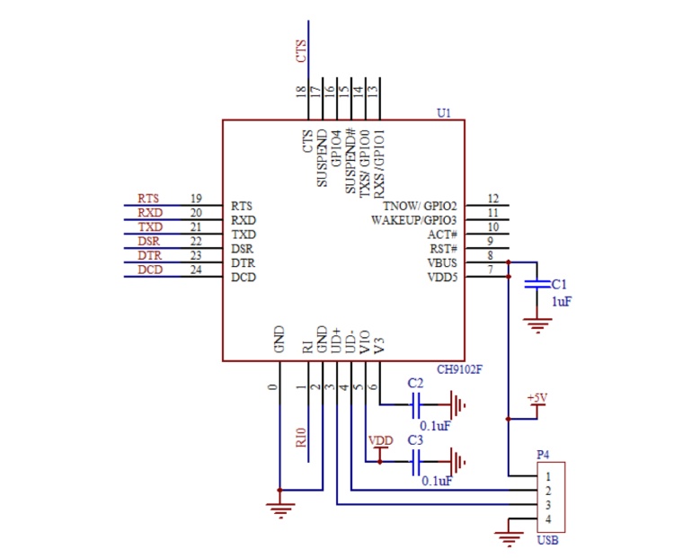
This circuit shows the basic configuration of the CH9102 IC, as you can see, the data lines of the USB are directly connected to the UD+ and UD- pins of the IC. The capacitors connected across the power supply is to stabilize the voltage and reduce the noise. We can connect the Tx and Rx lines of CH9102 to any microcontroller or similar circuits. Remember to connect the Tx to the Rx of the receiver and the Rx to the Tx of the receiver. Also, make sure that the grounds are commonly connected.
Having Troubles with CH9102?
I made a USB-to-serial converter using CH9102, but I am unable to communicate?
It's due to several reasons but you can check these:
- Double-check all connections between the CH9102 chip and the other components of your circuit. Make sure that the TX and RX lines are connected correctly to the devices you are trying to communicate with.
- Check that the voltage levels of the signals (TX, RX, etc.) are compatible with the devices you are connecting to.
- Sometimes, the issue could be with the USB cable itself. Try using a different USB cable to see if that resolves the problem.
How to test CH9102?
Make sure that the serial settings (baud rate) on your computer match those of the device you are trying to communicate with. Try connecting the TX and RX pins of the CH9102 together (a loopback test). Send some data from your computer, and if it's received correctly, it indicates that the CH9102 is working.
My computer is not recognizing the IC.
- Make sure that you have the correct drivers installed for the CH9102 chip on your computer. The drivers are necessary for the computer to recognize and communicate with the chip.
- In Windows, check the Device Manager to see if the CH9102 is recognized correctly without any error messages. If there are errors, it could indicate a driver issue or a problem with the hardware connection.
CH9102 PCB Design Choices
What are the design considerations when designing a PCB using CH9102?
- Place the USB port near the CH9102 IC, and the data lines track should route straight forward. The D+ and D- signal lines are placed close to the parallel wiring, and ground or copper should be provided on both sides to reduce signal interference from the other parts.
- Minimize the via count in data lines.
- Should use filter capacitors and also keep all components tightly.
Applications of CH9102
- Microcontroller Programming
- Debugging and Testing
- Industrial Control Systems
- DIY Electronics Projects
- Legacy Device Support
- Automation and Robotics
- USB to RS485 conversion.
- USB to RS232 conversion.
- USB to TTL serial port conversion.
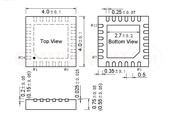
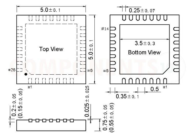
2D Model and Dimensions of CH9102
Here you can find the mechanical drawings of CH9102 along with its dimensions. The dimensions can be used to create custom footprints of the module and be used for PCB or CAD modelling.