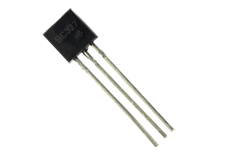
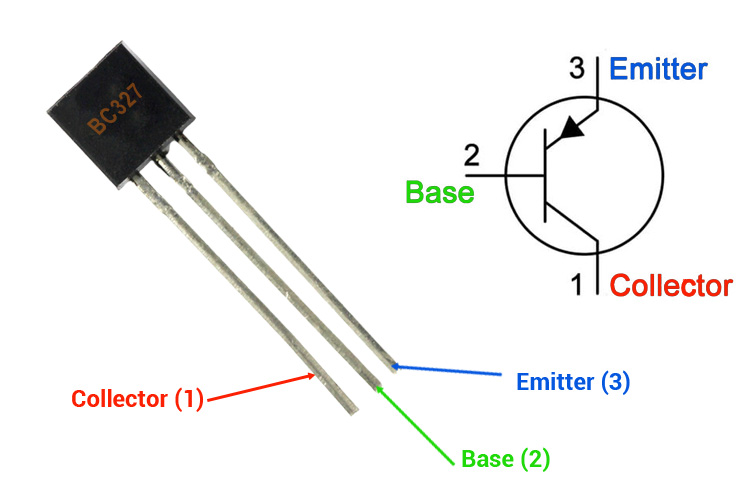
BC327 PNP General Purpose Transistor
BC327 is a general purpose PNP Transistor, the base of which needs to be connected to the ground, to turn on the transistor. This transistor is available in various versions and is manufactured by many different companies, that’s why, the gain of the transistor may vary depending upon the version of the transistor. So, it's recommended to check out the datasheet of the device before proceeding with the application and the datasheet for this specific transistor can be found on the bottom of the page.
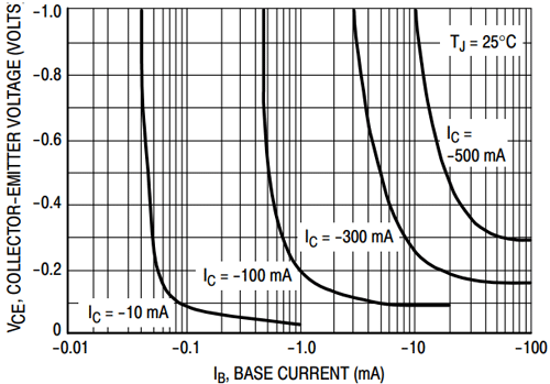
When the transistor is turned off, we can see a positive voltage on the transistor's base, if we measure the voltage between the base and the emitter. Based on the characteristics of the transistor, a minimum amount of current needs to flow out of the base to turn the transistor on and that is when a positive voltage appears on the base, leakage current starts to flow from the base to the ground. The characteristic curve below shows that a minimum of -10mA current needs to flow through the base to flow -300mA of collector current.
The below diagram shows the correlation between base current and collector current.
BC327 Pinout Configuration
|
Pin Number |
Pin Name |
Description |
|
1 |
Collector |
Electrons Emitted from Emitter Collected by the Collector |
|
2 |
Base |
Controls the biasing of the transistor |
|
3 |
Emitter |
Electrons emitted from the emitter into the first PN junction |
Basic Overview and Features
- Bi-Polar, High Voltage PNP Transistor
- DC Current Gain (hFE) is 250 ~ 630
- Continuous Collector current (IC) is -800mA
- Base-Emitter on Voltage -1.2V
- MAX Base- Emitter Voltage (VBE) is -5V
- Collector-Emitter Voltage (VCE) is -45V
- Available in To-92 Package
- Switching and Amplifier Applications
- Suitable for AF-Driver Stages and Low-Power Output Stage
- Compliment to BC337/BC338
Note: Complete Technical Details can be found at the BC327 datasheet given at the end of this page.
BC327 Equivalent Transistor
2N4403, BC488, BC638, 2N4402, 2N3702, 2N3703, BC486, BC490, BC328
Basic Working of a Transistor
The BC327 Transistor is a general-purpose PNP transistor, in which holes are the primary charge carrier of the device. When the base of the transistor is connected to the ground, leakage current starts to flow out of the base to the ground and the depletion region at the base of the transistor starts to shrink and more and more electrons start migrating from the collector to the emitter and into the circuit thus current flows constantly through the circuit.
How to use BC327 Transistor
Unlike MOSFETs, transistors are current-controlled devices, which means they can be turned on or off by supplying the required base current (for the BC327 transistor it’s -10mA). BC327 is a PNP transistor that means it will conduct when it’s connected to the ground and it will turn off when the base is connected to 5V.
The simulated circuit below shows how this transistor behaves when a base current is applied and when no current is provided to the base.
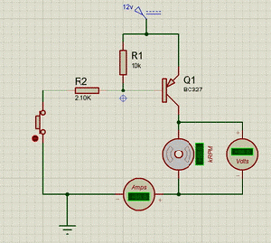
When we turn on the transistor by connecting the base to the ground the transistor will remain on unless the voltage at the base of the transistor reaches more than 1.2V. The base of the transistor cannot be left floating otherwise there could be false triggering to the transistor which may lead to issues in the circuit. To resolve this issue, we need to add pullup resistors, for example, in the above case, a 10K resistor is used to pull up the base of the transistor.
In the above example, we are using BC327 as a simple switching device and we have used a small 12V motor as a load. The small button here is for providing the trigger to the transistor and can be removed to leave simple contacts to touch. The 10KΩ resistor is for limiting the current to base and to avoid breaching maximum voltage allowed at the base and 2.1KΩ resistor is for limiting the current flowing out of base to ground.
Applications
- Switching relates and Lad’s
- PWM driven application
- LED dimmers or flashers
- Switching Applications
- Preamplifier for Power Amplifier
- Microphone preamplifiers
- Relay drivers
2D Model and Dimensions
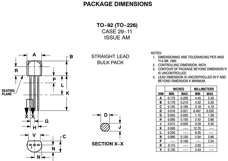
If you are designing a PCB or Perf board with this component, then the following picture from the Datasheet will be useful to know its package type and dimensions.
