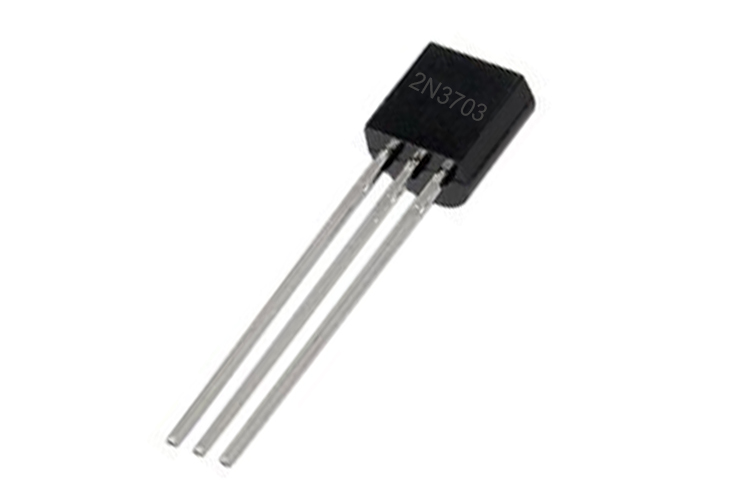
2N3703 General Purpose PNP Transistor
The 2N3703 is a PNP Transistor with VCE of -30V and a collector current of 500mA. It can be used as a small signal switching transistor and any other small-signal application. It also has a low base voltage of -5V.
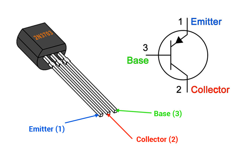
2N3703 Pinout Configuration
|
Pin Number |
Pin Name |
Description |
|
1 |
Emitter |
Electrons emitted from the emitter into the first PN junction |
|
2 |
Collector |
Electrons Emitted from Emitter Collected by the Collector |
|
3 |
Base |
Controls the biasing of the transistor |
Features & Specifications
- Bi-Polar PNP Transistor
- DC Current Gain (hFE) is in between 30 - 150 maximum
- Continuous Collector current (IC) is 300mA
- Emitter Base Voltage (VBE) is -5V
- Available in TO-92 Package
- Maximum Collector-Base Voltage |Vcb|: -50 V
- Collector Dissipation: 0.625 W
- Transition Frequency:100 MHz
- Operating and Storage Junction Temperature Range -55 to +150 °C
- Collector Capacitance 12pF
Note: Complete Technical Details can be found in the 2N3073 datasheet given at the end of this page.
2N3073 Equivalent Transistor
2N3702, BC108, BC558,2N3072,S8550, 2SA1943, BC556
Basic Working of a PNP Transistor
The 2N3073 transistor is a general-purpose PNP transistor, PNP transistor is made up of a doped N-Type material that is sandwiched in between two P-Type materials. In a PNP transistor hole are the majority charge carrier that means the holes are emitted by the collector and collected by the emitter, the main difference between the NPN and PNP transistor is the flow of electrons runs from collector to emitter but in a PNP transistor the electrons run from emitter to collector, as a result, a PNP transistor turns on when there is a low or 0V on the base of the transistor. That means the transistor turns on when a small amount of current flows through the collector to the emitter.
General Description of 2N3073 Transistor
The 2N3073 is a PNP Transistor, hence we need to provide zero volts to the base of the transistor to turn it on. This transistor comes with many different versions, if you are using this transistor as an amplifier make sure you check the gain of the transistor from the datasheet that can be found down below, because of different versions the gain value differs which can completely ruin your calculations. The maximum collector current of this transistor is rated at -500mA, and the collector cut-off current and emitter cut-off current is 100nA respectively, this transistor has an emitter-base saturation voltage of -5V. This transistor has a collector-emitter voltage of -30V and a collector base voltage of -50V. This transistor can operate with 150*C.
2N3073 Transistor has a gain of 30 to 150 this value determines the amplification capacity of the transistor, the peak current that can be flown through this transistor is 500maA. To bias a transistor, we have to supply current to the base pin, this current (IB) should be limited to 5mA, and the voltage across the base-emitter pin should be 5V. This stage is called the Saturation Region and the typical voltage allowed across the Collector-Emitter (VCE) or Base-Emitter (VBE) could be 30V and 5V respectively. When the base current is removed the transistor becomes fully off.
How to use 2N3073 Transistor
Transistors are current-controlled devices so to turn them on/off a little current is needed. For the 2N3073 Transistor, this current is less than 5mA, as 2N3073 is a PNP transistor that means it will be on when the base is connected to the ground, and it will be off when a positive voltage is applied to the base of the transistor.
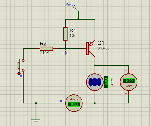
The simulated circuit above shows how this transistor behaves when the base of the transistor is pulled up to the VCC to the supply with a pullup resistor. As you can clearly observe the transistor is off and the motor is not spinning.
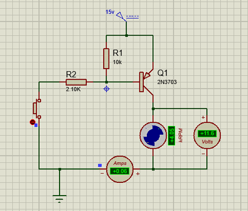
When we turn on the transistor by connecting the base to the ground (in our case we have used a 0V probe in proteus) the transistor will remain on unless the voltage at the base of the transistor reaches more than the base turn off voltage, for this transistor, it is somewhere in between 0.7 -0.9V. The base of the transistor cannot be left floating otherwise there could be false triggering, which may lead to issues in the circuit. To resolve the issue we need to add pull-up resistors as shown in the example a 10K resistor is used to pull up the base of the transistor to VCC.
Applications of 2N3073 Transistor
- Build simple audio circuits
- General-purpose amplifier
- Driver Modules like Relay Driver, LED driver, etc..
- Amplifier modules like Audio amplifiers, signal Amplifiers, etc..
- Darlington pair
2D Model of 2N3073 Transistor
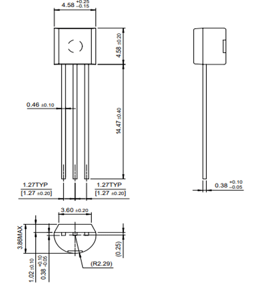
If you are designing a PCB or Perf board with this component then the following picture from the Datasheet will be useful to know its package type and dimensions.