IRF1405 N-Channel Power MOSFET

IRF1405 is a TO-220 N-channel MOSFET, specially designed for automotive applications. This MOSFET achieves extremely low-ON resistance per silicon area. The power MOSFET IRF1405 is compatible at 175˚C operating junction temperature.
IRF1405 has advanced features like fast switching speed and improved repetitive avalanche rating. These advantages make IRF1405 an extremely efficient and reliable device in automotive applications and other variety of applications.
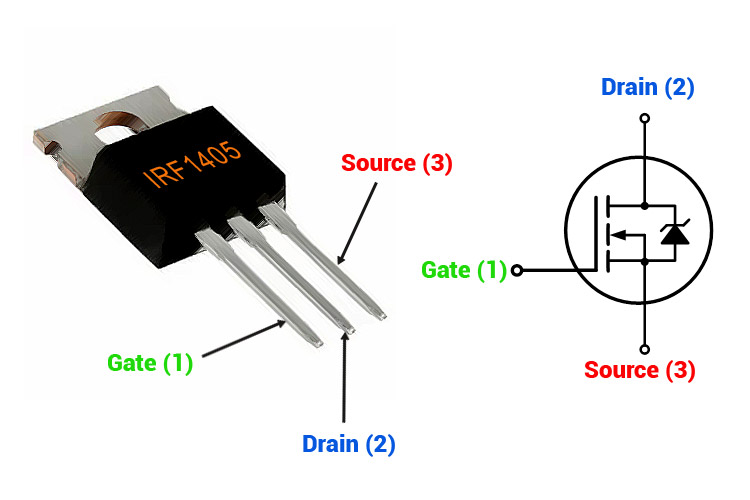
IRF1405 Pinout Configuration
IRF1405 is a three-terminal device. And three-terminals of MOSFET are Gate (G), Drain (D), and Source (S). The pin configuration of IRF1405 is shown in the table below.
|
Pin No. |
Pin Name |
Pin Description |
|
1 |
Gate (G) |
Controls the biasing of the MOSFET |
|
2 |
Drain (D) |
Current flows in through the Drain |
|
3 |
Source (S) |
Current flows out through Source at leaves MOSFET |
IRF1405 Equivalent
IRF034, IRF044, IRF044SMD, IRF054, IRF054SMD, IRF100B201
IRF1405 MOSFET Features
|
Parameter |
Rating |
|
Continuous Drain Current (ID)-@25˚C |
169 A |
|
Continuous Drain Current (ID)-@100˚C |
118 A |
|
Power Dissipation (PD) |
330 W |
|
Drain-to-source Breakdown voltage (VDD) |
55 V [min] |
|
Drain-to-source ON-Resistance (RDS) |
5.3 mΩ [max] 4.6 mΩ [typ] |
|
Gate-to-Source Voltage (VGS) |
±20 V |
Note: More technical specifications can be found in the IRF1405 MOSFET datasheet provided at the bottom of this page.
Special Benefits
The benefits of IRF1405 are listed below.
- Low ON resistance
- Dynamic dv/dt rating [peak diode recovery dv/dt = 5 V/ns (max)]
- 175˚ operating temperature
- Fast switching
- Repeating avalanche
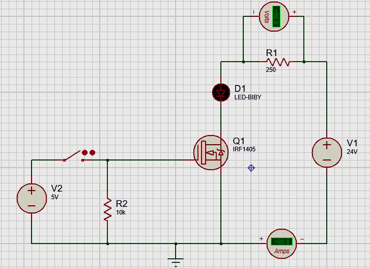
IRF1405 MOSFET Working with Simulation
Let’s make a switching circuit with the help of IRF1405. This device is an N-channel MOSFET and it is a voltage control device. It means, if the gate-to-source voltage is sufficiently available, the device will turn ON. And if a gate-to-source voltage is not available, the device will remain turn OFF condition. To simulate this, we will make a simple example circuit for IRD1405 in Proteus as shown below

Condition-1 Gate-to-Source voltage VDS = 5V
In this condition, when we turn ON the switch, the current will pass through the load and LED. Once MOSFET is turned ON, it will remain ON until the gate voltage is 0 V.

Condition-2 Gate-to-Source voltage VDS = 5V
In this condition, gate-to-source is zero. Hence, the MOSFET remains in OFF condition and the current will not pass through load and LED.
Applications
MOSFET IRF1405 is used in automobile applications. Some of them is as listed below.
- Electric Power Steering (EPS)
- Anti-locking Breaking System (ABS)
- Wiper Control
- Climate Control
- Power Door
2D Model and Dimensions