DRV8833 Dual H-Bridge Motor Driver Module
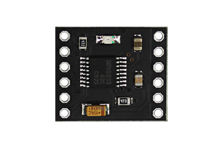
The DRV8833 Module is a two-channel H-bridge motor driver breakout board that can be used to drive two DC motors or one stepper motor. It has a total of 12 pins, four of which are output and four of which are input. Each output can supply up to 2A peak current with internal limiting, with overcurrent, overtemperature, short-circuit and undervoltage protection.
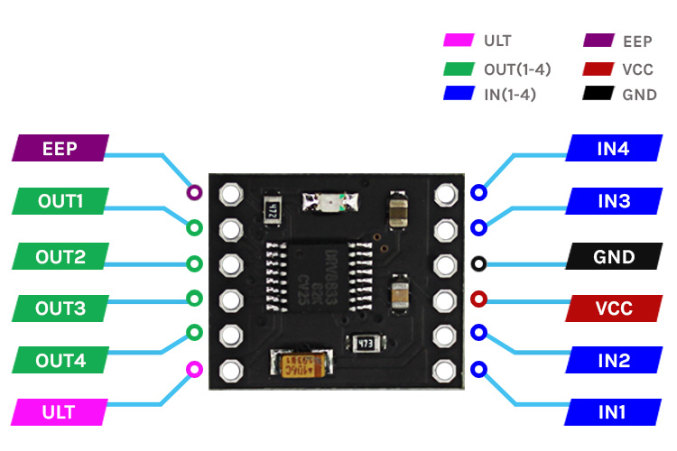
DRV8833 Module Pinout
|
Pin Number |
Pin Name |
Pin Description |
|
1 |
EEP |
Sleep mode input, active high |
|
2 |
OUT1 |
First output of the 1’st H-Bridge |
|
3 |
OUT2 |
Second output off the 1’st H-Bridge |
|
4 |
OUT3 |
First output of the 2’nd H-Bridge |
|
5 |
OUT4 |
Second output off the 2’nd H-Bridge |
|
6 |
ULT |
Logic low when in fault condition |
|
7 |
IN1 |
Logic input controls state of OUT1 |
|
8 |
IN2 |
Logic input controls state of OUT2 |
|
9 |
VCC |
Supply Voltage (Range 2.8 - 10.8V) |
|
10 |
GND |
Supply Ground |
|
11 |
IN3 |
Logic input controls state of OUT3 |
|
12 |
IN4 |
Logic input controls state of OUT4 |
DRV8833 Features and Descriptions
- Dual-H-Bridge Current-Control Motor Driver
- 1.5-A RMS, 2-A Peak per H-Bridge
- Parallel Output Configuration for 3-A RMS, 4-A Peak
- Wide Power Supply Voltage Range 2.7 to 10.8 V
- PWM Winding Current Regulation and Current Limiting
- Thermally Enhanced Surface-Mount Packages
Note: Complete technical details can be found in the DRV8833 datasheet linked at the end of this page.
DRV8833 Equivalents
TB6612, DRV8823
Other Motor Drivers
L6219, L298
How To Use DRV8833?
The DRV8833 is a dual channel H-bridge motor driver that can drive two DC motors or one stepper motor. It can supply up to 1.5A continuous current and 2A peak current and has internal overcurrent protection. DRV8833 dual DC motor control circuit diagram shown below,
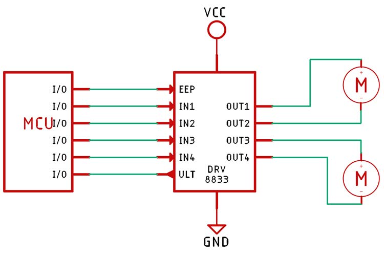
The motors can be controlled by IN1, IN2, IN3, and IN4 pins. By using a microcontroller the speed of the motors can be controlled. The table below shows the function of each pin.
|
State |
IN1/IN3 |
IN2/IN4 |
|
Forward |
High |
Low |
|
Reverse |
Low |
High |
|
Stop |
Low |
Low |
|
Stop |
High |
High |
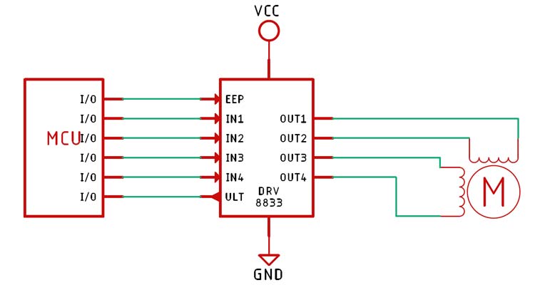
The DRV8833 can also be used to drive stepper motors with the following circuit diagram.
Applications
- Battery powered toys
- POS printers
- Security cameras
- Gaming machines
- Robotics
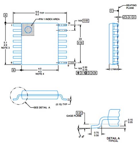
2D Model and Dimensions
If you are designing a PCB or Perf board with this component then the following picture from the DRV8833 Datasheet will be useful to know its package type and dimensions.