LTC2942 - High-Precision Power and Energy Monitor
The LTC2942 is a high-precision power and energy monitor manufactured by Analog Devices. It is capable to monitor the voltage, charge, and temperature. The LTC2942 is perfect for single-cell lithium-ion batteries The IC communicates over an I2C interface, making it easy to integrate into various digital circuits and microcontrollers. The LTC2942 IC needs only one resistor to monitor the current. The integrated coulomb counter integrates the current flowing through the resistor that is connected between the positive terminal of the battery and the load, and we can measure the charge. Also, the IC can measure the battery voltage and the on-chip temperature using an internal 14-bit analog-to-digital converter (ADC). The measured charge, voltage, and temperature are stored in internal registers, we can access this via the I2C interface. The LTC2942 is designed to operate with low power consumption and comes in a small 6-pin DFN package, making it suitable for battery-powered applications.
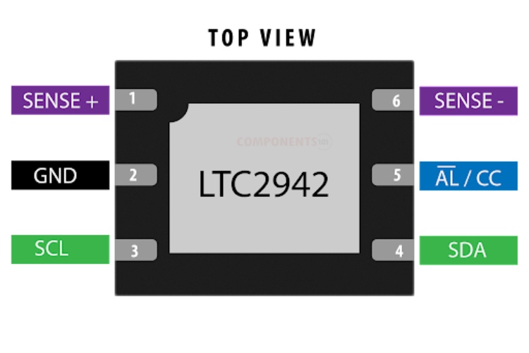
LTC2942 Pinout Configuration
Here are the pinout details for the LTC2942.
| PIN NO | PIN NAME | DESCRIPTION |
| 1 | SENSE+ | Positive Current Sense Input and Power Supply. |
| 2 | GND | Device Ground. Connect directly to the negative battery terminal |
| 3 | SCL | Serial Bus Clock Input. |
| 4 | SDA | Serial Bus Data Input and Output. |
| 5 | AL/CC | Alert Output or Charge Complete Input |
| 6 | SENSE– | Negative Current Sense Input |
Manufacturers of LTC2942
LTC2942 is manufactured only by Analog Devices
LTC2942 Equivalents
If you are looking for an equivalent or replacement for LTC2942 you can use the LTC2941 from the same family.
LTC2942 Alternatives
If you are looking for an alternative for LTC2942 you can look at the other IC from these.
INA219 (INA219 module), MAX17205, MCP39F511, MAX14720, ISL28022, LTC4150
Note: Complete technical details can be found in the LTC2942 datasheet at this page’s end.
Features of LTC2942
LTC2942 has the following key features:
- Indicates Accumulated Battery Charge and Discharge
- High Accuracy Analog Integration
- ADC Measures Battery Voltage and Temperature
- Integrated Temperature Sensor
- 1% Voltage and Charge Accuracy
- ±50mV Sense Voltage Range
- SMBus/I2C Interface
- Configurable Alert Output/Charge Complete Input
- 2.7V to 5.5V Operating Range
LTC2942 Schematics
The following image shows the typical LTC2942 circuit diagram.
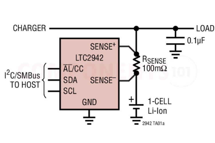
The following image shows the typical LTC2942 application (Single-Cell Lithium-Ion Coulomb Counter with Battery Charger for Charge and Discharge Currents of Up to 500mA) circuit diagram.
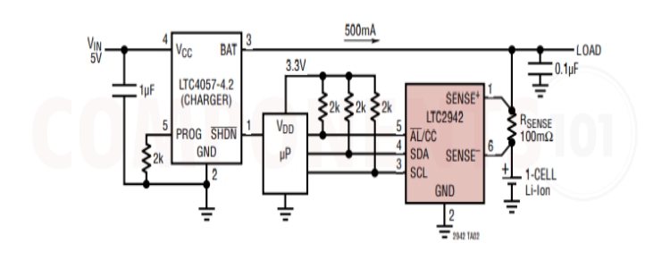
In this circuit, the LTC2942 is connected to a microcontroller via I2C pins also the alarm pin is connected, all these pins are pulled high using the pull-up resistors. The LTC4057 charges the single-cell battery with a maximum current of 500mA. we can monitor the charging current, voltage and temperature using the controller.
Troubleshooting Tips for LTC2942
- Battery voltage issue. The LTC2942 is designed for use with single Li-Ion cells and other battery types with a terminal voltage of 2.7V to 5.5V. Above this Maximum Ratings may cause permanent damage to the device.
- Current and voltage sense problem: All currents into pins are positive, and all voltages are referenced to the ground.
- Current Sensing not working properly: Should Connect a low-value shunt resistor in series with the load to measure current. Make sure the shunt resistor value is within the range supported by the LTC2942 (typically 10mΩ to 200mΩ).
- I2C communication not working. Use pull-up resistors (typically 10kΩ) while connecting with the microcontroller the SDA and SCL pins of the LTC2942.
Design Tips for LTC2942
Is it possible to use the LTC2942 without a microcontroller?
No, since the communication is i2c we can't use the IC without a microcontroller.
Is it possible to Charge and monitor a 12V lead acid Battery with LTC2942?
No. The LTC2942 is designed for use with single Li-Ion cells (2.7V to 5.5V).
What are the design considerations when designing a PCB using LTC2942?
Keep all traces as short as possible to minimize noise and inaccuracy. Use a 4-wire Kelvin sense connection for the sense resistor, locating the LTC2942 close to the resistor with short sense traces to the SENSE+ and SENSE– pins. Use wider traces from the resistor to the battery, load and/or charger. Put the bypass capacitor close to SENSE+ and GND.
Does it have Reverse polarity protection?
No. make sure that your battery is in its correct polarity, otherwise it will damage the IC.
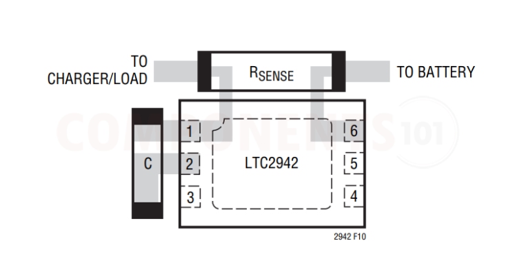
Recommended PCB Layout
Here is the manufacturer-recommended PCB layout for LTC2942.
Applications of LTC2942
- Low-Power Handheld Products
- Cellular Phones
- MP3 Players
- Cameras
- GPS
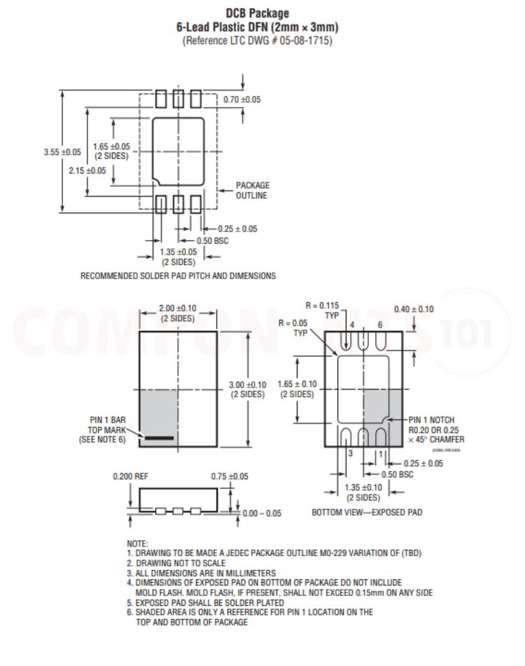
2D Model and Dimensions of LTC2942
Here you can find the mechanical drawings of LTC2942 along with its dimensions. The dimensions can be used to create custom footprints of the module and be used for PCB or CAD modelling.