LTC2400 24-Bit µPower No Latency Delta-Sigma ADC
The LTC2400 is a high-precision, 24-bit analog-to-digital converter (ADC) Analog Devices. It has high accuracy, low noise performance and high resolution. The LTC2400 uses delta-sigma technology for its analog-to-digital conversion, this gives high resolution and low noise performance, making them suitable for precision measurement applications. Additionally, the LTC2400 is designed to provide single cycle settling time, which is beneficial for multiplexed applications where rapid switching between input channels is required without losing accuracy. The internal oscillator of LTC2400 requires no external frequency setting components and perfectly works with any external reference voltage from 0.1V to VCC. The LTC2400 features a pin that allows for the configuration of rejection frequency. By default, the pin configuration provides better than 110dB rejection at either 50Hz or 60Hz ±2%, which is useful for rejecting mains frequency interference. The LTC2400 communicates through a flexible 3-wire digital interface which is compatible with SPI and MICROWIRETM protocols. This IC is available in the SO-8 package.
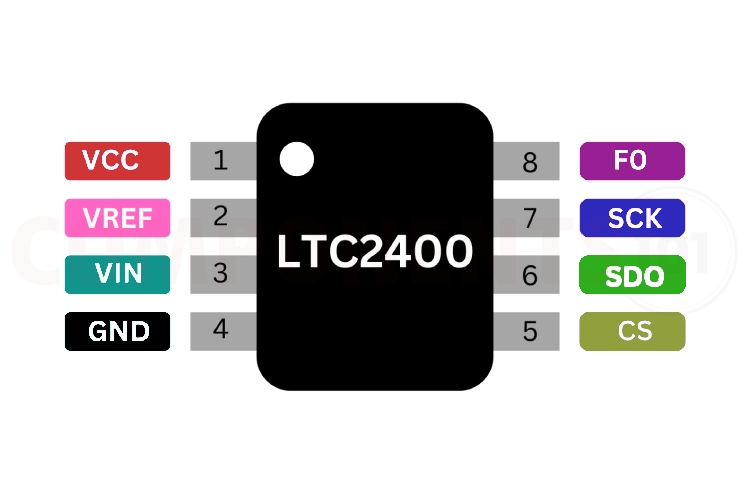
LTC2400 Pinout Configuration:
Here are the pinout details for LTC2400.
| PIN NO | PIN NAME | DESCRIPTION |
| 1 | VCC | Positive supply Voltage |
| 2 | VREF | Reference Input |
| 3 | VIN | Analog Input. |
| 4 | GND | Ground |
| 5 | CS | Active LOW Digital Input |
| 6 | SDO | Three-State Digital Output |
| 7 | SCK | Bidirectional Digital Clock Pin |
| 8 | F0 | Frequency Control Pin |
LTC2400 Features:
LTC2400 ADC has the following key features:
- 24-Bit ADC Resolution
- SO-8 Package
- 4ppm INL, No Missing Codes
- 4ppm Full-Scale Error
- Single Conversion Settling Time for Multiplexed Applications
- 0.5ppm Offset
- 0.3ppm Noise
- Internal Oscillator—No External Components Required
- 110dB Min, 50Hz/60Hz Notch Filter
- Reference Input Voltage: 0.1V to VCC
- Live Zero—Extended Input Range Accommodates 12.5% Over range and Under range
- Single Supply 2.7V to 5.5V Operation
- Low Supply Current (200µA) and Auto Shutdown
How to Identify LTC2400?
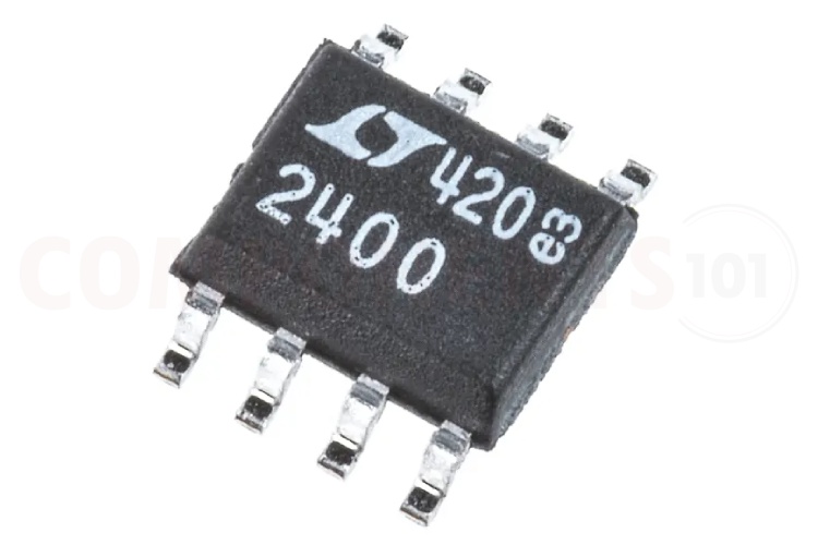
The LTC2400 comes with 2 different markings, 2400 and2400I. And they can be ordered with the part numbers LTC2400CS8#PBF, LTC2400IS8#PBF, LTC2400CS8#TRPBF or LTC2400IS8#TRPBF.
Manufacturers of LTC2400:
The LTC2400 is manufactured by Analog Devices (earlier this IC was from Linear Technology). There are no alternative manufacturers for the same part number as of the date of writing this article.
LTC2400 Equivalents
There is no pin-to-pin compatible equivalent or replacement for LTC2400.
LTC2400 Alternatives
If you are looking for an alternative for LTC2400 you can look at the other IC from these.
AD7791, HX711, MCP3008, ADS1115, ADC0804, MCP3301, ADC0831, ADS1015.
Note: Complete technical details can be found in the LTC2400 datasheet at this page’s end.
LTC2400 Schematics
The following image shows the LTC2400 application circuit diagram.
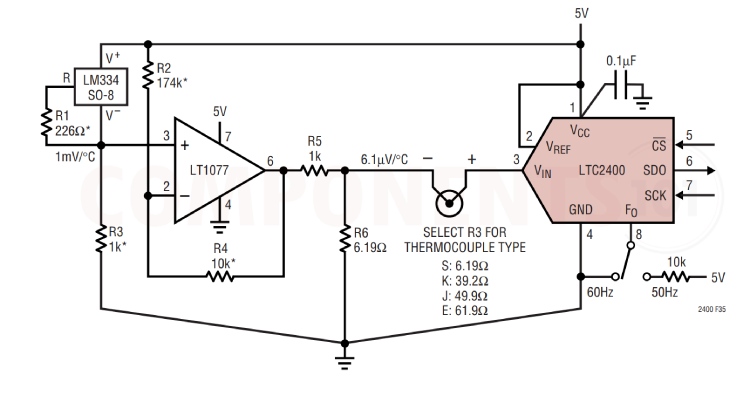
The circuit shows an inexpensive thermocouple sensing circuit with the removal of the DC offset. The output of the LT1077 is attenuated in order to produce the required coefficient, as well as reduce the noise and offset error contribution. If used with a thermistor, this circuit can be modified to produce curvature correction. The removal of the offset associated with diode forward voltage, or the 273°K overhead on some monolithic temperature sensors, simplifies the use of substantial gain after the thermocouple. Chopper amplifiers such as the LTC1050 can extend the noise floor of the LTC2400 by as much as a factor of 10 to 20. The use of a gain of 20 in front of the LTC2400 can extend the resolution of a thermocouple application to 0.02°C or better. If absolute accuracy is not important, the use of a low-noise bipolar amplifier, such as the LT1028, can extend the resolution an additional order of magnitude. Note that achieving high accuracy in the circuit in Figure 36 requires a calibration sequence for circuit offset and gain correction.
Troubleshooting Tips for LTC2400
- The circuit’s performance is not stable. There is a lot of noise introduced to the line: Ensure that the power supply to the LTC2400 is stable and within the specified voltage range. Connect a 1uf capacitor in between the supply voltage pin and the ground.
- SPI communication is not working: First check the hardware connections. Check whether the spi pins are connected correctly to the microcontroller. Then check the programming side.
- Not getting any signals from the IC: Make sure that the LTC2400 is powered correctly according to the specified voltage levels and current requirements. Double-check all the connections, including SPI lines, reference voltage inputs, and analog input signals, to ensure they are properly connected. Verify that the clock signal to the LTC2400 is within the specified frequency range and has the correct waveform.
Design Tips for LTC2400:
1. How to minimize noise while using LTC2400?
Good decoupling is important when using high-resolution ADCs. Vcc should be decoupled with 1 µF capacitors to GND. To achieve the best from these decoupling components, they should be placed as close as possible to the device, ideally right up against the device.
2. How to give reference voltage?
We can use any external voltage divider/ regulator to provide reference voltage. Make sure that the grounds of ADC and voltage provider are connected. Also, check whether the reference voltage is in the range.
3. Is it possible to use this IC in the breadboard?
Since the IC is available only in the SO-8 package, so you can't directly connect the IC into the breadboard. You can use a suitable adapter for connecting to the breadboard. While using a breadboard for building the circuit, ensure that the components are in nearby to the ADC ic.
Applications of LTC2400
- Weight Scales
- Direct Temperature Measurement
- Gas Analyzers
- Strain-Gage Transducers
- Instrumentation
- Data Acquisition
- Industrial Process Control
- 6-Digit DVMs
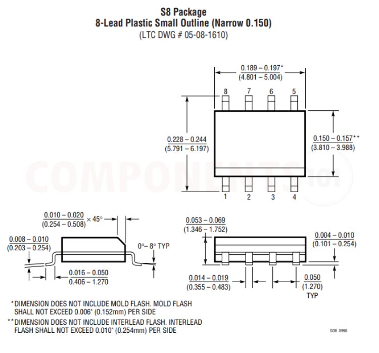
2D Model and Dimensions of LTC2400
Here you can find the mechanical drawings of LTC2400 along with its dimensions. The dimensions can be used to create custom footprints of the module and be used for PCB or CAD modelling.