MCP3301 13-Bit, 100kSPS, Single Channel ADC
The MCP3301 is a single-channel 13-bit Analog to Digital Converter (ADC) from Microchip. The MCP3301 uses an industry-standard SPI interface enabling a faster stream of conversion results. The SPI interface also makes it easier to interface the ADC chip with any microcontroller that is equipped with this standard serial bus. It also features a full differential input and low power consumption. The small package size along with the above features makes it ideal for battery-powered systems and remote data acquisition applications. The MCP3301 features 100k samples/second sample rate, 13-bit resolution, low power consumption (300 nA typical standby, 450µA maximum active), and is available in 8-pin PDIP, SOIC and MSOP packages. The full differential input of the MCP3301 enables a wide variety of signals to be used in applications such as remote data acquisition, portable instrumentation, and battery-operated applications.
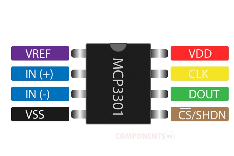
MCP3301 Pinout Configuration
Here are the pinout details for MCP3301.
| Pin Number | Name | Function |
| 1 | VREF | Reference Voltage Input |
| 2 | IN(+) | Positive Analog Input |
| 3 | IN(-) | Negative Analog Input |
| 4 | VSS | Ground |
| 5 | CS/SHDN | Chip Select / Shutdown Input |
| 6 | DOUT | Serial Data Out |
| 7 | CLK | Serial Clock |
| 8 | VDD | +4.5V to 5.5V Power Supply |
Features of MCP3301
MCP3301 ADC chip has the following key features:
- Full Differential Inputs
- 13-Bit resolution
- ±1 LSB max DNL
- ±1 LSB max INL (MCP3301-B)
- ±2 LSB max INL (MCP3301-C)
- Single supply operation: 4.5V to 5.5V
- 100 ksps sampling rate with 5V supply voltage
- 50 nA typical standby current, 1 µA max
- 450 µA max active current at 5V
- Industrial temp range: -40°C to +85°C
- 8-pin MSOP, PDIP, and SOIC packages
Manufacturers of MCP3301:
The MCP3301 is manufactured by Microchip. There are no alternative manufacturers for the same part number as of the date of writing this article.
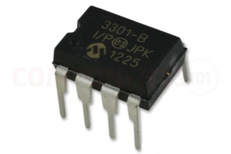
Decoding MCP3301 Parts Marking
You can use the image below to identify the MCP3301 parts marking.
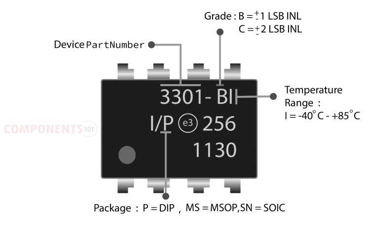
Examples:
- MCP3301-BI/P: ±1 LSB INL, Industrial Temperature, PDIP package
- MCP3301-BI/SN: ±1 LSB INL, Industrial Temperature, SOIC package
- MCP3301-BI/MS: ±1 LSB INL, Industrial Temperature, MSOP package
- MCP3301-CI/P: ±2 LSB INL, Industrial Temperature, PDIP package
- MCP3301-CI/SN: ±2 LSB INL, Industrial Temperature, SOIC package
- MCP3301-CI/MS: ±2 LSB INL, Industrial Temperature, MSOP package
MCP3301 Equivalents
If you are looking for an equivalent replacement for MCP3301, you could check out the MCP3001 from Microchip, it shares the same pinout. But the difference is that it is a 12-bit ADC with a 200 Ksps sampling rate while the MCP3301 is a 13-bit ADC with a 100 Ksps sampling rate. You can check out the MCP3302 and MCP3304 ADCs from Microchip. They have similar specifications as MCP3301, only difference is they have more analog channels, 2 for MCP3302 and 4 for MCP3304, and have different packages with higher pin counts.
MCP3301 Alternatives
If you are looking for an alternative for MCP3301 you can look at the other IC from these.
HX711, MCP3008, ADS1115, ADC0804.
Note: Complete technical details can be found in the MCP3301 datasheet at this page’s end.
MCP3301 Circuit Diagram
The following image shows a simple circuit diagram for MCP3301.
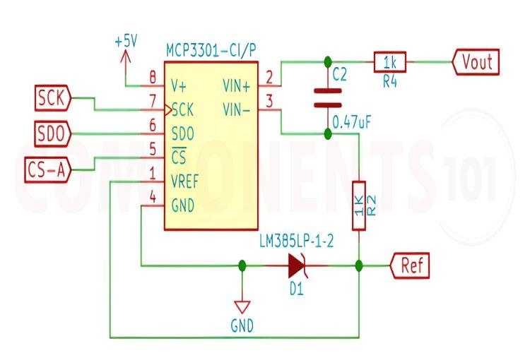
The whole circuit is powered from a 5V power supply. The reference voltage is applied to the Vref pin, and the input is connected to the differential input IN+ through a resistor. A capacitor is connected between the differential inputs and a 1K resistor is connected between the Vref and IN-. The serial interfacing pins can be connected to any host MCU to retrieve the conversion data from the ADC chip.
MCP3301 Troubleshooting Guide
My MCP3301 is not providing any output. What could be the issue?
First, ensure that the power supply voltages are within the specified range (typically 2.7V to 5.5V). Check the connections to the MCP3301, including VDD, VSS, and the reference voltage (VREF). Also, verify that the clock signal (CLK) and the chip select signal (CS) are correctly applied. Additionally, confirm that the analog input signal is within the specified input voltage range (typically 0V to VREF).
I'm experiencing erratic output from the MCP3301. What might be causing this?
Erratic output can be due to noise or interference in the system. Ensure that the analog input signal is adequately filtered and shielded from noise sources. Verify that the ground connections are solid and free from ground loops. Additionally, check the integrity of the clock signal (CLK) and ensure that it meets the MCP3301's timing requirements.
The MCP3301 seems to be providing inaccurate readings. How can I troubleshoot this issue?
Inaccuracy can result from various factors, including reference voltage drift, non-linearity, or offset errors. Verify that the reference voltage (VREF) is stable and within the specified accuracy. Consider calibrating the system if necessary. Check the analog input signal for any offset or noise. Also, ensure that the MCP3301 is configured correctly for the desired resolution and input range.
The MCP3301 is not responding to the SPI interface commands. What steps should I take to diagnose this problem?
Double-check the SPI interface connections, including MOSI (Master Out Slave In), MISO (Master in Slave Out), and SCK (Serial Clock). Ensure that the chip select (CS) signal is correctly toggled to select the MCP3301. Verify the timing and sequence of SPI commands according to the MCP3301 datasheet. It may also be helpful to monitor the SPI signals with an oscilloscope to detect any anomalies.
I suspect a hardware failure in my MCP3301. How can I confirm this?
To diagnose a potential hardware failure, you can perform continuity checks on the MCP3301's pins and verify that they are properly connected to the rest of the circuit. Check for any visible signs of damage, such as burnt components or solder joints. If possible, test the MCP3301 in a different circuit setup or replace it with a known working unit to isolate the issue. Additionally, consult the MCP3301 datasheet and application notes for further guidance on troubleshooting specific problems.
Things to Consider When using MCP3301 in your Design:
When designing with the MCP3301, a 13-bit Analog-to-Digital Converter (ADC), here are some important considerations and design tips to keep in mind:
Reference Voltage (VREF): Ensure a stable and accurate reference voltage (VREF) is provided to the MCP3301. This voltage determines the full-scale range of the ADC's conversion. Use a low-drift, low-noise voltage reference for improved accuracy. Filter the VREF signal to minimize noise and maintain stability.
Analog Input Signal Conditioning: Protect the MCP3301's analog input pin from voltage levels outside the specified range (typically 0V to VREF). Provide appropriate filtering and buffering for the analog input signal to reduce noise and ensure signal integrity. Consider using anti-aliasing filters to remove high-frequency components before sampling to prevent aliasing.
Clock and Timing Considerations: Ensure that the clock signal (CLK) meets the MCP3301's timing requirements specified in the datasheet. Use a stable and accurate clock source to maintain ADC performance. Minimize clock jitter and skew to avoid errors in sampling.
Power Supply Decoupling and Layout: Implement proper power supply decoupling with capacitors placed close to the MCP3301 to provide stable voltage rails and reduce noise. Follow recommended layout guidelines from the MCP3301 datasheet to minimize signal interference, crosstalk, and ground loops. Pay attention to analog and digital ground separation to prevent digital noise coupling into the analog circuitry.
SPI Interface Considerations: Ensure proper configuration of the Serial Peripheral Interface (SPI) bus, including data format, clock polarity, and phase settings. Implement robust error detection and handling mechanisms, such as CRC checks or timeout mechanisms, if necessary. Consider using hardware SPI peripherals available on microcontrollers for efficient communication with the MCP3301.
Temperature and Environmental Considerations: Consider the operating temperature range and environmental conditions in which the MCP3301 will be used. Use appropriate thermal management techniques if operating in high-temperature environments to maintain accuracy and reliability.
Applications of MCP3301
- Remote Sensors
- Battery-operated Systems
- Transducer Interface
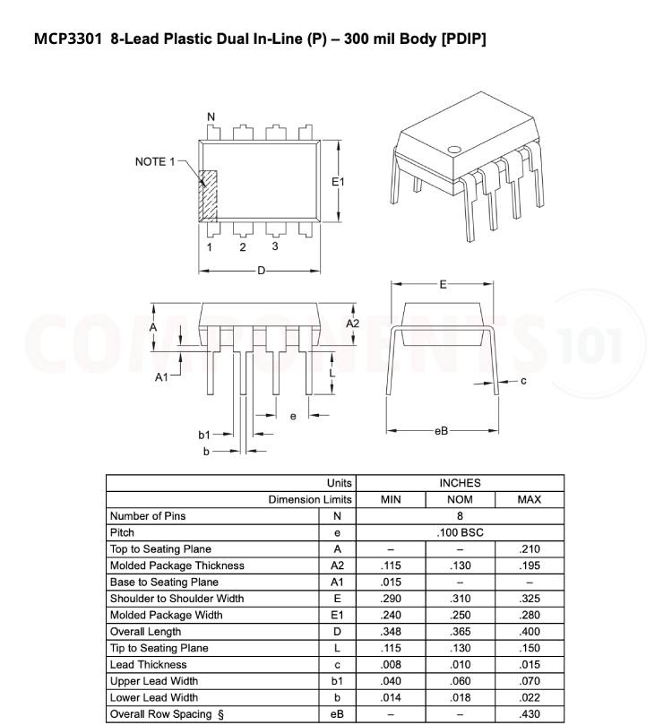
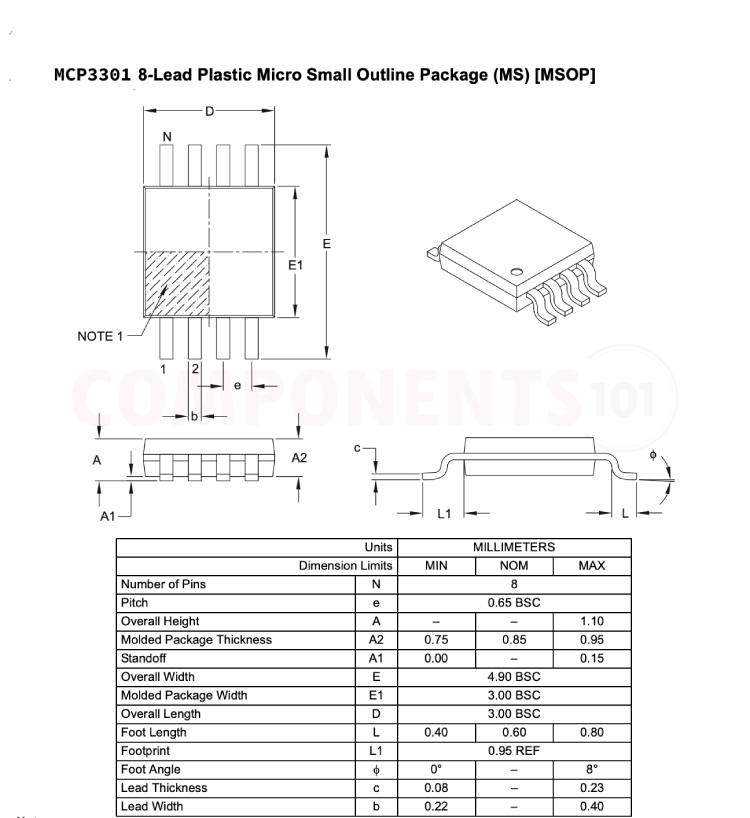
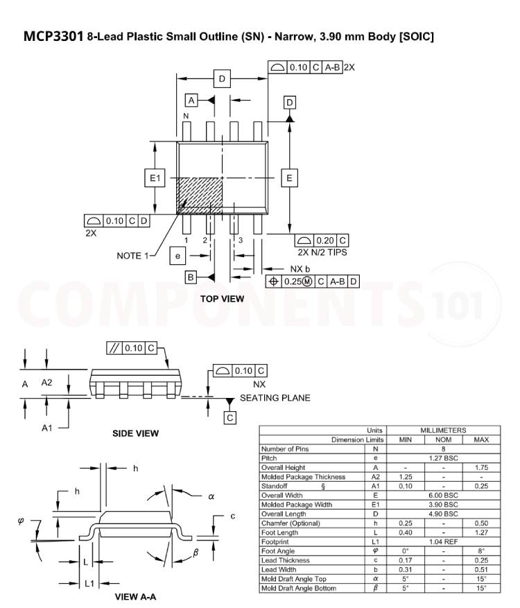
2D Model and Dimensions of MCP3301
Here you can find the mechanical drawings of MCP3301 along with its dimensions. The dimensions can be used to create custom footprints of the module and be used for PCB or CAD modelling.