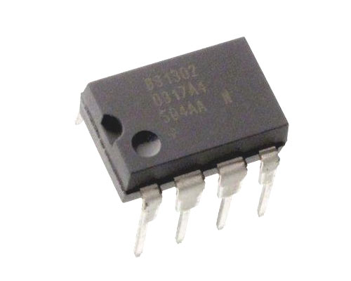
DS1302 RTC Chip
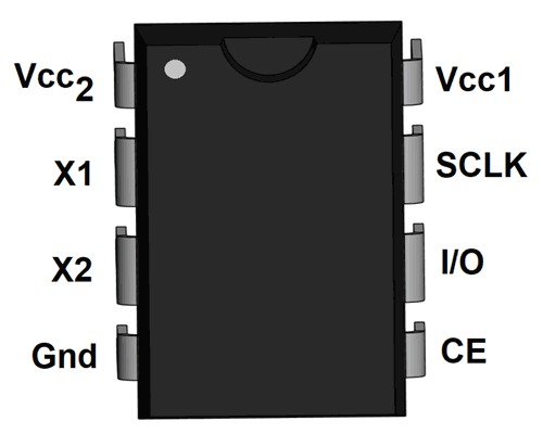
DS1302 Pin Configuration
|
Pin No. |
Pin Name |
Description |
|
1 |
Vcc2 |
Second supply input, when Vcc2 is greater than Vcc1 + 0.2V, DS1302 powers through this pin |
|
2,3 |
X1 and X2 |
For connecting an external crystal oscillator of 32.768kHz |
|
4 |
GND |
Ground |
|
5 |
CE |
This pin is set to HIGH during a Read or a Write |
|
6 |
I/O (Data Line) |
This is the bi-directional data pin to the 3-wire interface |
|
7 |
SCLK(Serial Clock) |
Used to synchronize data movement on the serial interface |
|
8 |
Vcc1 |
Rechargeable energy source connected to this pin |
Features
- Real-time clock counts minutes, seconds, date, hours, month day of the week, year, and leap-year compensation upto 2100.
- Single and Multiple (Burst mode) data transfer for Read and Write of Clock or RAM data
- 31*8 battery-backed general-purpose RAM
- Simple interface using 3-wire
- TTL-compatible
- 2V to 5.5V full operation
- Compact size
- Available Package: 8-pin DIP, 8-pin SO
Technical Specifications
- Supply voltage (typically): 3.3V
- Voltage range on any pin (with respect to ground): -0.5V to 7.0°C
- Operating Temperature (Commercial): 0°C to +70°C
- Operating Temperature (Industrial): -40°C to +85°C
- Storage Temperature range: -55°C to +125°C
- Soldering Temperature: 260°C
Note: Complete technical information can be found in the DS1302 Datasheet linked at the bottom of this page.
Brief about DS1302 Chip and DS1302 RTC Module
DS1302 is a tickle-charge timekeeping chip that contains a real-time clock/calendar and 31 bytes of static RAM. DS1302 uses serial communication to interact with microcontrollers. Also, it automatically adjusts the date for the month with fewer days. The clock operates in 24hr or 12hr format with an AM/PM indicator.
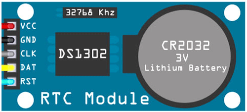
DS1302 chip is also commonly used as a DS1302 RTC module which comes with a 32 kHz crystal and on-board battery backup all in a small SIP module that is compatible with a breadboard. DS1302 modules are used by makers with Arduino, Raspberry Pi, and other Microcontrollers.
A DS1302 RTC module pinout is shown in the below image.
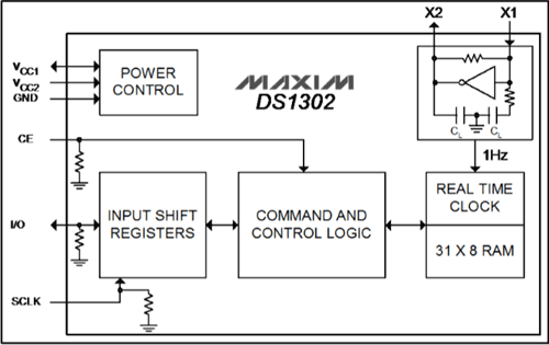
Block Diagram of DS1302 RTC Chip
How to Use a DS1302 Chip
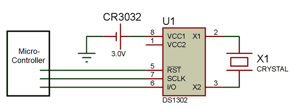
A typical operating circuit for DS1302 is given below. DS1302 have two power input, one is from cell and other is from controller. A crystal oscillator of 32.768 kHz is used to generate required frequency. For interfacing Data line, Reset Pin and Serial-clock pins of DS1302 are connected with the micro-controller.
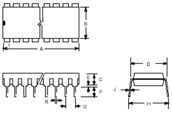
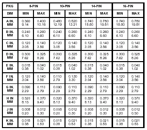
2D-model and Dimensions