AMS1117 1A LDO Regulator – Fixed/Variable
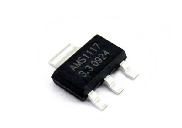
The AMS1117 is a popular SMD package 3-pin voltage regulator that is available in many models for fixed and adjustable voltage requirements. The IC can deliver a maximum current of 1A and the output voltage can vary from 1.5V to 5V. It also has a low drop out voltage of 1.3V when operating at maximum current.
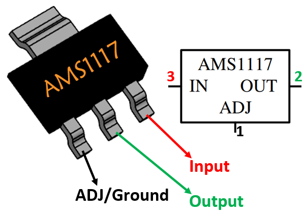
Pin Configuration
|
Pin Number |
Pin Name |
Description |
|
1 |
Adjust/Ground |
This pins adjusts the output voltage, if it is a fixed voltage regulator it acts as ground |
|
2 |
Output Voltage (Vout) |
The regulated output voltage set by the adjust pin can be obtained from this pin |
|
3 |
Input Voltage (Vin) |
The input voltage which has to be regulated is given to this pin |
Features
- Fixed/Adjustable 3-terminal Linear voltage regulator
- Low Drop-Out (LDO) Voltage regulator
- Fixed Voltage type: 1.5V, 1.8V, 2.5V, 2.85V, 3.3V and 5V
- Variable Voltage range: 1.25V to 13.8V
- Output current is 1000mA
- Maximum Drop-out Voltage: 1.3V
- In-built Current Limiting and thermal protection.
- Operating junction temperature is 125°C
- Available in SOT-223, TO-252 and SO-8 Package
Note: Complete Technical Details can be found at the datasheet provided at the end of this page.
Alternative Voltage Regulators: LM317, LM7805, NTE9060
Alternative for AMS1117: LM1117
Where to use AMS1117
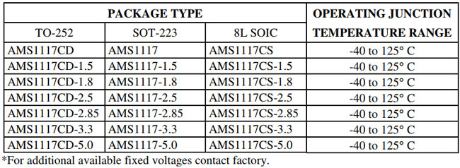
Just like the famous 7805, LM317 the AMS1117 is also another Linear Voltage regulator. It is known for its small form factor since it is available as a DCY Package (SMD Component). There are many types of LM1117, based on package and output voltage. But all the IC is rated for a maximum current of 1A. The below table will help you choose the right part number for your IC.
The IC is popularly known for being used in Arduino boards to regulate 5V and 3.3V. So if you are looking for a SMD component voltage regulator then this IC might be the right choice for you.
How to use AMS1117
Using the AMS1117 is pretty much straight forward. If it a fixed voltage regulator just power the IC though the Vin pin and the regulated output can be obtained in the Vout pin. The Adj/Ground pin in this case acts only as a ground pin and is grounded. Also a capacitor can be added at the output side to filter out the noise. The circuit diagram for a variable output regulator is show below
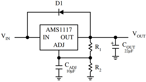
For an Adjustable type voltage regulator we need two external resistors to decide the output voltage of the Regulator. A reference circuit diagram for adjustable voltage is shown below, where the resistors R1 and R2 decides the output voltage of the regulator. The capacitor CAdj is an optional component which can be added to improve ripple rejection if required. The other two capacitors are to filter the input and output noise respectively.
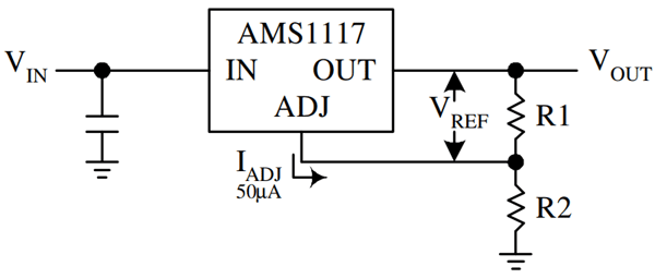
The formulae to calculate the output voltage of AMS1117 regulator is given below. Select the value of R1 and R2 based on the output voltage required for your project. Keep in mind that the value of R1 should be less than 1k. You can use a variable resistor at R2 if you want to vary the voltage in real time.
VOUT = VREF (1 + R2/R1) + IADJR2
With the ability to be used as a fixed voltage or a variable voltage regulator the AMS1117 often finds its application in battery charging circuit and can also be designed to provide negative voltage if required. Refer the datasheet at the end of this page to find more application circuits for this IC.
Applications
- Used for Positive voltage regulations
- Variable power supply
- Current limiting circuits
- Reverse polarity circuits
- Commonly used in Desktop PC, DVD and other consumer products
- Used in motor control circuits
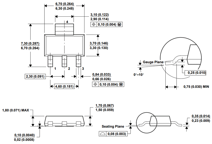
2D – Model of LM1117 (DCY Package)


Are you 18? Come in and don't be shy!