Soil Moisture Sensor Module
This soil moisture sensor module is used to detect the moisture of the soil. It measures the volumetric content of water inside the soil and gives us the moisture level as output. The module has both digital and analog outputs and a potentiometer to adjust the threshold level.
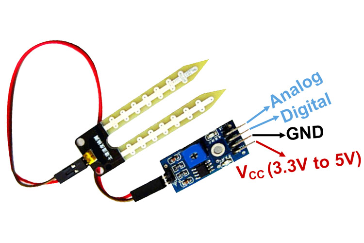
Soil Moisture Sensor Module Pinout Configuration
|
Pin Name |
Description |
|
VCC |
The Vcc pin powers the module, typically with +5V |
|
GND |
Power Supply Ground |
|
DO |
Digital Out Pin for Digital Output. |
|
AO |
Analog Out Pin for Analog Output |
Soil Moisture Sensor Module Features & Specifications
- Operating Voltage: 3.3V to 5V DC
- Operating Current: 15mA
- Output Digital - 0V to 5V, Adjustable trigger level from preset
- Output Analog - 0V to 5V based on infrared radiation from fire flame falling on the sensor
- LEDs indicating output and power
- PCB Size: 3.2cm x 1.4cm
- LM393 based design
- Easy to use with Microcontrollers or even with normal Digital/Analog IC
- Small, cheap and easily available
Alternate Sensor Modules: IR Sensor Module, LDR Sensor Module, Flame Sensor Module, TP4056A Li-ion Battery Charging/Discharging Module, DS3231 RTC Module, TMC2209 Stepper Motor Driver Module, DRV8825 Stepper Motor Driver Module, A4988 Stepper Motor Driver Module, NEO-6MV2 GPS Module, Joystick Module, EM18 - RFID Reader Module, ADXL335 Accelerometer Module, HMC5883L Magnetometer Module
Related Components: LM393 Comparator IC, 10K Potentiometer, Capacitor
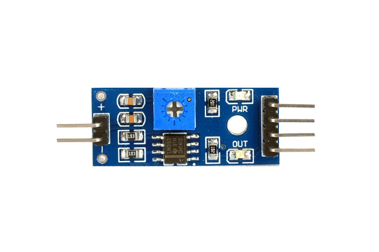
Brief about Soil Moisture Sensor Module
This Moisture sensor module consists of a Moisture sensor, Resistors, Capacitor, Potentiometer, Comparator LM393 IC, Power and Status LED in an integrated circuit.
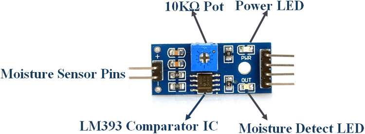
LM393 IC
LM393 Comparator IC is used as a voltage comparator in this Moisture sensor module. Pin 2 of LM393 is connected to Preset (10KΩ Pot) while pin 3 is connected to Moisture sensor pin. The comparator IC will compare the threshold voltage set using the preset (pin2) and the sensor pin (pin3).
Moisture Sensor
The moisture sensor consists of two probes that are used to detect the moisture of the soil. The moisture sensor probes are coated with immersion gold that protects Nickel from oxidation. These two probes are used to pass the current through the soil and then the sensor reads the resistance to get the moisture values.
Preset (Trimmer pot)
Using the onboard preset you can adjust the threshold (sensitivity) of the digital output.
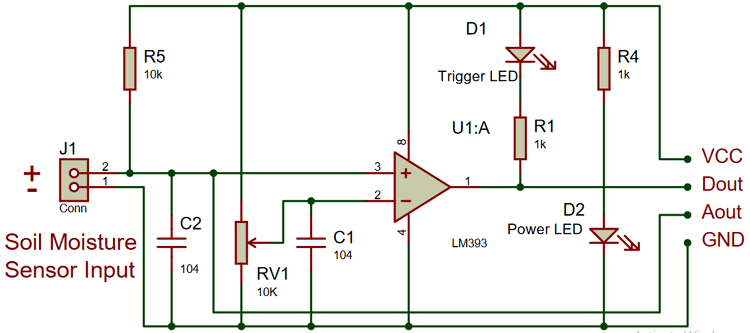
How to Use Soil Moisture Sensor Module
Moisture sensor module consists of four pins i.e. VCC, GND, DO, AO. Digital out pin is connected to the output pin of LM393 comparator IC while the analog pin is connected to Moisture sensor. The internal Circuit diagram of the Moisture sensor module is given below.
Using a Moisture sensor module with a microcontroller is very easy. Connect the Analog/Digital Output pin of the module to the Analog/Digital pin of Microcontroller. Connect VCC and GND pins to 5V and GND pins of Microcontroller. After that insert the probe inside the soil. When there is more water presented in the soil, it will conduct more electricity that means resistance will be low and the moisture level will be high.
Applications of Soil Moisture Sensor
- Gardening
- Irrigation Systems
- Used in Controlled Environments


how much area can the soil…
how much area can the soil moisture sensor measure? pls answer