TDA2030 Audio Amplifier
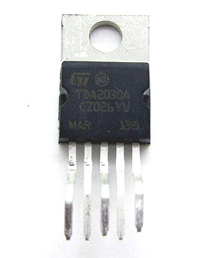
The TDA2030 IC is a powerful audio amplifier IC able to deliver up to 20W of output power, so you can use it to run a 4Ω speaker at 12W or a 8Ω speaker at 8W.
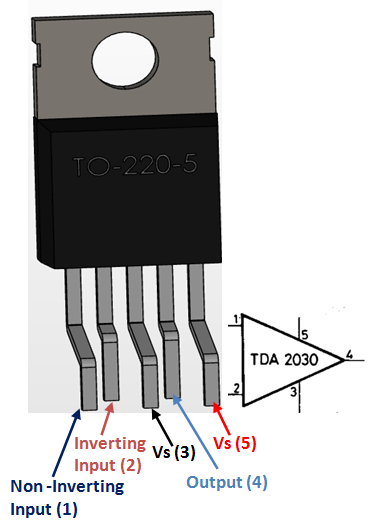
TDA2030A Pinout Configuration
|
Pin Number |
Pin Name |
Description |
|
1 |
Non – Inverting Input |
Non inverting end (+) of Amplifier |
|
2 |
Inverting Input |
Inverting end (-) of Amplifier |
|
3 |
Vs (Ground) |
Connect to the ground of the circuit |
|
4 |
Output |
This pin outputs the amplified signal |
|
5 |
Vs (Power) |
Supply voltage, Minimum 6V and Maximum 36V |
Features
· Low frequency class AB amplifier most suited for audio amplification
· Can provide up to 20 Watts as output power
· Wide range of power supply from 6V to 36V
· Short circuit and thermal protection is available
· Breadboard friendly
· Available in 5-pin TO220 package
Note: Complete Technical Details can be found at the TDA2030A datasheet given at the end of this page.
TDA2030A Equivalent Audio Amplifiers
TDA2050, NTE1380, LM386
Where to use a TDA2030 amplifier?
The TDA2030 is a powerful audio amplifier IC. An audio amplifier is nothing but one that has the capability to amplify the audio signals from any audio source such as mobile phone jack or microphone so that volume is increased when the audio is played in a speaker. Audio amplifier circuits can also be made using simple op-amps, but if you need higher volume that is loud enough for a room then this power audio amplifier is will be the best choice. This IC can deliver up to 20W of output power, so you can run a 4Ω speaker at 12W or a 8Ω speaker at 8W.
How to use TDA2030?
The TDA2030 is breadboard friendly and hence can be easily tested using a breadboard. The TDA2030A datasheet given at the bottom of this page consists of some basic circuits which can be used to make this IC work. I have also given a very basic circuit below.
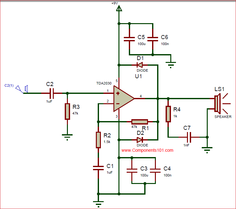
The IC can wither work on dual power supply or single mode power supply, to keep this simple I have preferred single mode supply by using a 9V battery. The 5th pin (Vs) is connected to the positive terminal of the battery and the 3rd pin (Ground) is connected to the negative terminal of the battery. This IC is a power amplifier IC and hence requires a decent amount of current to operate, hence make sure your battery can source enough current.
The resistor R1 and R2 forms a potential divider across the pins 4 and 2. The two diodes D1 and D2 are used to protect the IC from reverse currents. The speaker LS1 can be any ordinary speaker of value 4Ω, 6Ω or 8Ω. The audio source C2(1) can be any audio source from a mobile jack or even a microphone. Just connect the positive point to C2(1) and ground the other point. Also note that this amplifier can amplify only mono channel sound signals. So if you have two audio wires for left and right channel combine them both to make it as a single channel.
Applications
· Used for Audio signal Amplification
· Suitable for high power amplification
· Capable of operating on dual/split power supply
· Can be used to cascade audio speakers
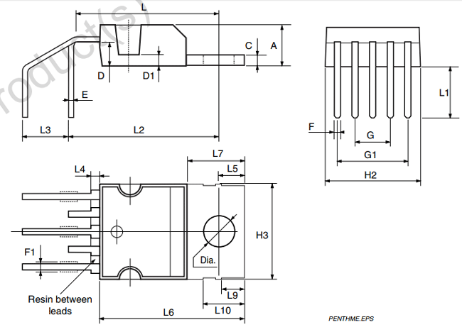
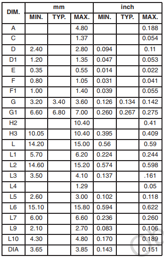
2-D Model (PDIP)


Capacitors
Why capacitors C3 and C4 are just hanging on earth? They are just idle, or I don't understand something?