

Optimized with highly sensitive cap touch sensors, extensive peripheral circuits and 125℃ operation
Introduction to Motor Driver: H-Bridge Topology and Direction control
The most commonly used actuator in any electronic device/machine will be motors next to solenoids, pneumatics and hydraulics. From a simple vibration motor inside a mobile phone to complex stepper motors in CNC machines, these DC machines can be found everywhere. To control a motor using a Microcontroller or processors we need something called a Motor Driver or Motor Controller. Depending upon the type of motor and type of control required the type of Motor Drivers will also change. In this article we will focus only of DC motors and how to control a DC motor using a Motor Driver with the most popular H-bridge Topology. This technique will help us drive small or large DC Motors and also control its direction.
What is motor driver IC
The motor driver IC is an integrated circuit chip used as a motor controlling device in autonomous robots and embedded circuits. L293D and ULN2003 are the most commonly used motor Driver IC that is used in simple robots and RC cars. A motor driver is undoubtedly something that makes the motor move as per the given instructions or the inputs (high and low). It listens to the low voltage from the controller/processor and control an actual motor which needs high input voltage. In simple words, a motor driver IC controls the direction of the motor based on the commands or instructions it receives from the controller. Many motor drivers follow different topology, in this article we will focus on the popular H-bridge topology which is used in the L293D motor driver IC.
Why do we need motor driver IC
As the world is witnessing new technology every day, autonomous robots are one of them. We use these ICs in autonomous robots mainly to control them. Microprocessors operate on low-level voltage/current, unlike motors. For example the popular Arduino microcontrollers or PIC microcontroller has an operating voltage of 5V or 3.3V, but a decent DC motor requires 5V or 12V to operate.
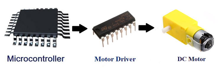
In this case if we want to supply the power to the motor, we need a high voltage. But we know that microprocessor output is low, and it cannot give enough power from its I/O pin to drive a motor. To supply this voltage/current from microprocessor to the motor, we need this Motor driver IC in between our motor and controller.
How the motor driver works
Motor driver receives signals from the microprocessor and eventually, it transmits the converted signal to the motors. It has two voltage pins (VCC1 and VCC2), and one of them is used to turn on the motor driver, and another pin is used to apply the voltage to the motor through this motor IC. This motor IC will continuously toggle the output signal according to the input wave it is receiving from the microprocessor.
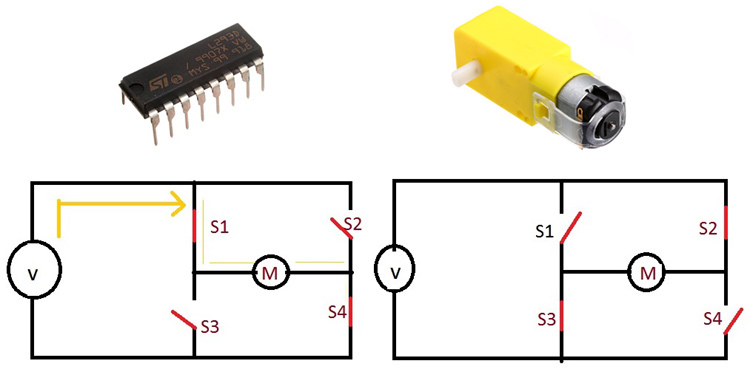
The small IC transmits the signal it receives, but it will not change the value of the signal. For example, if the microprocessor sends a high input (1) to the Driver Ic then, driver Ic will pass the same High (1) though it's an output pin. The H-bridge circuit will look like this in the picture below. Four switches will form an ''H'' shape, and these four switches are used to enable/disable the supply.
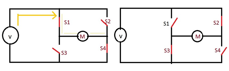
Rotate in clockwise direction
Now, in the first condition, when S1 and S4 switches are closed, and S3 and S2 are open, the voltage will pass from the S1 switch to the Motor and then to the S4. Hence we have a complete circuit that will allows current to flow from V to M through S1 and S4. This state will be a short circuit in S1 and S4 switch condition. In this case, the Motor will be in ON, and the direction of the Motor will be in a clockwise rotation.
Rotate in counter-clockwise direction
Coming to the Next state, when we enable S3 and S2 by giving voltage input, then the S1 and S4 switches will close, and the voltage travels from S3 and S2. This is also a positive connection by enabling two parallel-connected switches, but the rotation of the Motor will be in a counter-clockwise direction.
How to turn off the Motor (Braking)
To turn off the Motor, either we can turn off the voltage supply, or we can open all the switches in Motor. And note that you can only turn on two parallel connected switches at a time. And when we close S1 and S3 switches, Motor will receive only the positive signal from two sides, and it has no direction to send the ground signal. As a result, Motor will get into the ‘STALL’ condition. The direction of the motor rotation will be based on the inputs we are giving and also the switches we opened in the circuit.
Advantages of Motor Driver IC
- High level functionality and better performance
- The circuit is easy to operate. So, we can easily control the robot using inputs.
- It can be used in autonomous and commercial robots, as well.
- The motor deals with heavy current. Due to this current flow, IC gets heated, and we need a heatsink to reduce the heating.
- We use 4 capacitors in this circuit to avoid the fluctuations of voltage while using the motor in one direction and suddenly when we take the opposite direction. This works as a direction shifter without loss.


