Arduino UNO Q bridges high-performance computing with real-time control.
Voltage Controlled Oscillator Using 555

VCO Explained - What is a Voltage Controlled Oscillator?
A Voltage Controlled Oscillator (VCO) is an electronic oscillator whose oscillation frequency is controlled by a voltage input. It will create an oscillating signal with an output frequency that is proportional to the control voltage. The voltage-controlled oscillators are fundamental in many applications, they are used in applications including signal generators, signal modulations such as Fm and PM, and phase-locked loops such as frequency synthesizers for communication and audio synthesizers for music production.
How Does a Voltage Controlled Oscillator Work?
A Voltage Controlled Oscillator operates on the principle that the frequency of oscillation is a function of the input control voltage. Essentially, the input voltage determines the rate at which the oscillator's output signal changes. This relationship allows for dynamic frequency adjustment, which is critical in applications like frequency modulation (FM), phase-locked loops (PLL), and function generators. By varying the control voltage, you can sweep through a range of frequencies, making it the optimal choice for many signal-processing tasks.
How to Make a Voltage Controlled Oscillator Using 555
As we know the classic 555 timer IC is a very robust component in electronics, that can be used to make many types of circuits with very few external components. In a previous article, we even learned how to make a square wave generator using a 555 timer. So, in this article, we will learn how to make a voltage-controlled oscillator or a VCO using the 555 timers.
Voltage Controlled Oscillator Circuit using 555 Timer
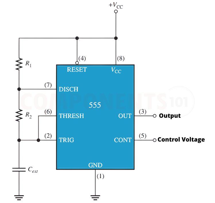
Here is a simple circuit diagram for a voltage-controlled oscillator using 555 timer IC.

Here as you can see the 555 timer is configured to operate in the astable mode, meaning it continuously oscillates between high and low states. The frequency of this oscillation is normally determined by the resistors and capacitors connected to it. But when used as a VCO we can change the frequency of oscillation by adjusting the control voltage, which will in terms change the threshold and trigger levels internally.
555 Timer Voltage Controlled Oscillator TinkerCAD Simulation
Here we have also prepared a ThinkerCAD simulation for you to try before making the live circuit.
To simulate the circuit, click on simulation and the simulation will be loaded. You can adjust the control voltage on the top power supply, and by doing that you can change the frequency. You can observe the resulting waveform on the oscilloscope window.
In the circuit, the external input voltage is applied to the control voltage pin 5 of the IC. The applied voltage can be varied from zero up to the maximum value of the supply voltage. Thus the output frequency of the multivibrator will proportionally vary with the voltage variation from 0 to 9V. The control voltage's value affects the values of the threshold and trigger voltages. As a result, the capacitor's charging period changes according to the control voltage. Therefore, any change in the control voltage will result in an increase or decrease in the capacitor's charging time, and consequently the output waveform's time period, effectively changing the frequency.
Voltage Controlled Oscillator Formula
The frequency of a 555 timer in astable mode is given by:
f=1.44(R1+2R2)C1
When configured as a VCO, the frequency is modulated by the control voltage (VC). The modified formula takes into account the control voltage:
f=1.44(R1+2R2)C11+VCVCC
Where:
- f= Output frequency
- R1 and R2 = Resistor values
- C1 = Capacitor
- VC = Control voltage
- VCC = Supply voltage
By adjusting the control voltage VC, you effectively change the oscillation frequency.


