

Optimized with highly sensitive cap touch sensors, extensive peripheral circuits and 125℃ operation
How to Choose the Right EMI Filter for your Design?
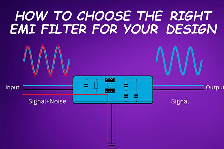
EMI (electromagnetic interference) is a common problem in electronic circuits that can cause unwanted noise and interference in electrical devices. Switch-mode power supplies are notorious for injecting EMI into the transmission line. The fast switching of high voltage and current nodes leads to relatively large di/dt values within the circuit, resulting in emission of EMI noises. EMI filters are designed to reduce or eliminate these unwanted signals, but choosing the right filter for a particular design can be a challenging task. In this article, we will discuss how to choose the right EMI filter for your design, including EMI filter design and calculation with an example.
EMI and Electromagnetic Compatibility (EMC)
There are typically three key components in electromagnetic compatibility (EMC): sources, paths, and receptors.
Sources refer to devices or circuit nodes that generate electromagnetic interference. This includes power supplies, microprocessors, video drivers, RF generators, and other similar devices. When a source produces noise, there are two possible paths it can travel. The first is a radiated path, where electromagnetic energy propagates through space and couples with other systems. The second is a conducted path, where the signal travels through the conductors of the system such as PCB traces, component leads, and input wiring. This can cause noise to be picked up by other equipment being powered from the same line.
Receptors are devices that detect and are affected by the interference emitted by the source. This can include both analog and digital circuits and is a crucial factor in ensuring that a system is electromagnetically compatible.
When conducting EMC testing, regulators typically examine conducted and radiated electromagnetic emissions separately. Each type of emission has its own limits and frequency range, along with its own suppression method. Radiated emissions cover a higher frequency range (typically 30 MHz to 1,000 MHz) and are difficult to control since they travel through space. To attenuate the noise at the source, proper circuit design techniques and layout must be used, as well as shielding to contain the radiated noise. On the other hand, conducted emissions cover a lower frequency range (typically 0.15 MHz to 30 MHz) and can be controlled through the use of electrical filtering components. When designing a system with EMI filtering, designers may choose to use off-the-shelf EMI filters or design their own discrete filters.
EMI Filter Design
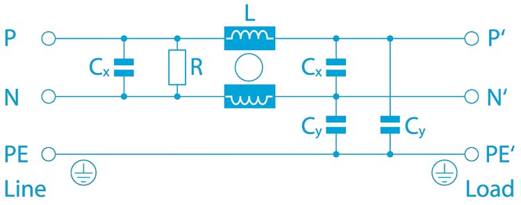
EMI filters are typically composed of capacitors, inductors, and resistors that are arranged in specific configurations to attenuate electromagnetic interference. There are three basic types of EMI filters: single-stage, multiple-stage, and feed-through filters.
Single-stage filters are the simplest and most common type of EMI filter, consisting of a single capacitor and inductor arranged in a specific configuration. Multiple-stage filters use multiple stages of capacitors and inductors to provide higher levels of attenuation. Feed-through filters are designed to be inserted between two printed circuit board (PCB) layers to filter out EMI signals.
When designing an EMI filter, several factors need to be considered, including the type of interference, the frequency range of the signals, and the amount of attenuation required. In general, EMI filters are designed to provide high levels of attenuation in the frequency range where the interference occurs, while allowing the desired signals to pass through with minimal attenuation.
Filter Parameters
While designing a custom EMI filter or while choosing an off the shelf EMI filters, there are few key parameters to consider. These parameters are crucial and can affect the performance of the filter as well as the connected circuitry if not selected properly.
- Rated voltage: This refers to the maximum voltage that can be applied to the input. For Exceeding this can damage the filter components as well as connected circuit. Example. Most single-phase filters are rated to 250VAC while 3-phase filters are rated to 480VAC.
- Rated current: This is the maximum continues current that the EMI filter is designed to carry without exceeding the safe temperature range. This should be higher than the maximum continues current that the connected device will draw at maximum load.
- Ambient Temperature: This refers to the highest temperature at which the filter is designed to carry the maximum rated current. Depending on the application area this can change.
- Operation temperature: This is the temperature range in which the filters can be safely operated. Most commercial off-the-shelf filters are designed to operate in a temperature range of -25°C to +85°C. Special applications such as military or industrial will have much higher temperature range.
- Leakage current: This is the current that flows through the earth. The EMI filters will contribute leakage current in addition to that of the connected device itself. There are regulations on the limit on leakage current and the designs should consider it based on the abiding safety regulation standards.
- Number of stages: It refers to the number of filter stages. A single-stage filter will have one filter circuit while multi-stage filters will have multiple filter circuits connected in stages. Increasing the number of stages improves filter performance while optimizing the filter package (size). It also helps to lower the cut off frequency.
EMI Filter Calculation with Example
To illustrate the process of EMI filter calculation, let's consider the example of a power supply circuit that needs to filter out unwanted EMI signals. The power supply has an output voltage of 5V and a maximum output current of 1A. The input voltage is 120VAC, 60Hz, and the power supply is designed to operate at a frequency range of 100kHz to 1MHz.
The first step in EMI filter calculation is to determine the frequency range of the unwanted signals. In this example, the frequency range is between 100kHz and 1MHz. The next step is to choose the appropriate EMI filter configuration based on the frequency range and attenuation requirements.
For this example, a multiple-stage EMI filter is chosen, consisting of three stages of capacitors and inductors. The first stage consists of a 10µF capacitor and a 10µH inductor in series. The second stage consists of a 1µF capacitor and a 1µH inductor in series. The third stage consists of a 0.1µF capacitor and a 0.1µH inductor in series.
Once the EMI filter configuration is chosen, the next step is to calculate the values of the components. The values of the capacitors and inductors are calculated based on the frequency range and attenuation requirements. In general, the capacitance and inductance values increase as the frequency of the unwanted signals increases.
For this example, the component values are calculated as follows:
First stage: C1 = 10µF, L1 = 10µH
Second stage: C2 = 1µF, L2 = 1µH
Third stage: C3 = 0.1µF, L3 = 0.1µH
After the component values are calculated, the EMI filter can be constructed and tested to ensure that it provides the desired level of attenuation. The performance of the filter can be measured using an oscilloscope or a spectrum analyzer to ensure that the unwanted signals are filtered out while the desired signals are passed through with minimal attenuation.
Now let’s look at a practical example. In thus we have used an online tool called Redexpert from Wurth electronics. The parameters we have used are as per below.
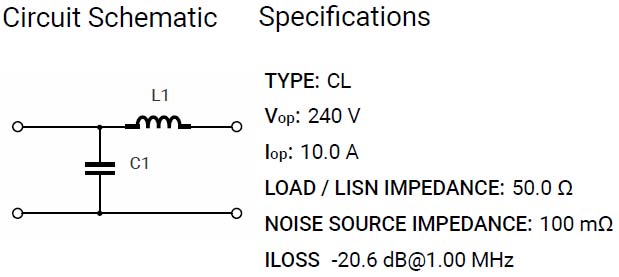
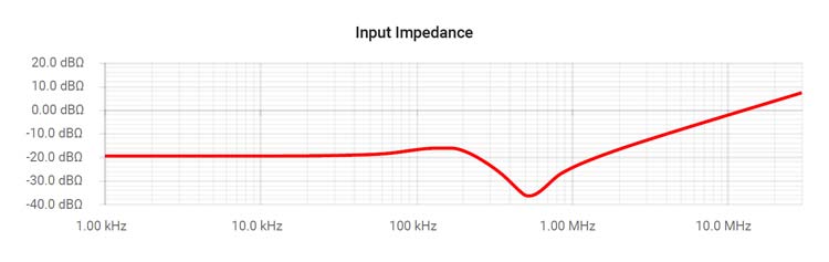
We have set the nominal voltage to 240V and max current to 10A. And set the insertion loss to -20dB at 1MHz. Value for the C1 is 6.8uF and L1 is 100nH. Here are the results.
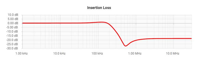
Here is the plot showing input impedances,
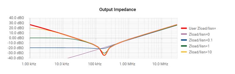
and output impedances.
Conclusion
EMI filters are essential components in electronic circuits that can help to reduce unwanted noise and interference. When choosing the right EMI filter for your design, it is essential to consider factors.


