

Optimized with highly sensitive cap touch sensors, extensive peripheral circuits and 125℃ operation
Understanding DIAC Working with Application Circuits
The most popular and commonly used Power Electronic Switching Devices are the BJT, MOSFET , and IGBT. But when it comes to switching AC waveforms, we can frequently notice the TRIAC being used to switch current in both directions. Now, since TRIACs cannot fire/trigger symmetrically it is accompanied by a support component called DIAC. A DIAC is a two-terminal device that can act as a switch based on the voltage applied across it. In this article, we will learn more about DIAC, its construction, working and application. So let get started......
What is DIAC?
The term DIAC stands for the DIode for Alternating Current (DIAC), it is a bidirectional semiconductor switch that can be turned ON in both forward and reverse direction. The device is a member of the Thyristor family and it is mostly used in triggering TRIAC and other Thyristor based circuits. The DIAC starts conducting electric current if the applied voltage goes beyond its break-over voltage.
DIACs are available in different types of DIAC packages such as discrete components in small leaded packages, surface-mount packages, large packages that are bolted to chassis and various other packages. Most of the time the DIAC and TRIAC are used together, so they are available in integrated packages also.
DIAC - Symbol
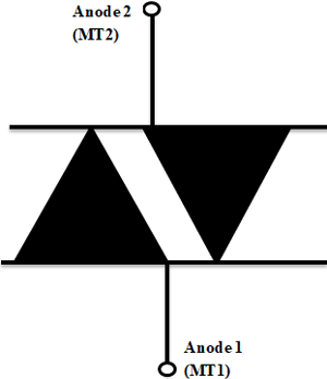
DIAC is given by the symbol of two Diodes connected in parallel and opposite to one another and has two terminals. Since the DIAC is bidirectional, we can’t name those terminals as anode and cathode, the terminals of DIAC are simply called A1 and A2 or MT1 and MT2 where MT stands for Main terminals. Hence the pinouts of DIAC are reversible just like a resistor or ceramic capacitor.
You could have noticed, although it belongs to the thyristor family it does not have a controlling gate terminal because they can be turned on or off by simply reducing the voltage level below the avalanche breakdown voltage and it can be done in both the polarities.
DIAC Construction
The construction of DIAC will be quite similar to the structure of the transistor, but they have some differences like the DIAC does not have any base terminal, all the three layers have the same amount of doping and it delivers symmetrical switching properties in both the polarities of the applied voltage.
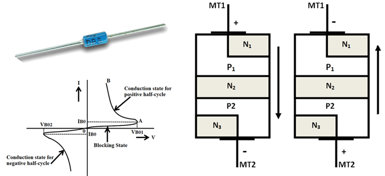
The above diagram shows the typical construction of the DIAC. As mentioned earlier the DIAC has two terminals namely MT1 and MT2 and it can deliver current flow in both directions. The DIAC is made of a five-layered structure; the layers closer to the terminals are the combination of both positive and negative layers. When the voltage is passed to the terminals the layer with respective polarity to the voltage gets activated, this combination of both the polarities helps in operating the DIAC in both the directions
DIAC Working Principle
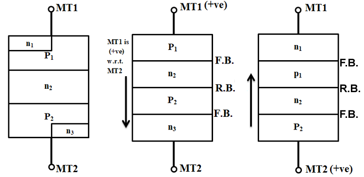
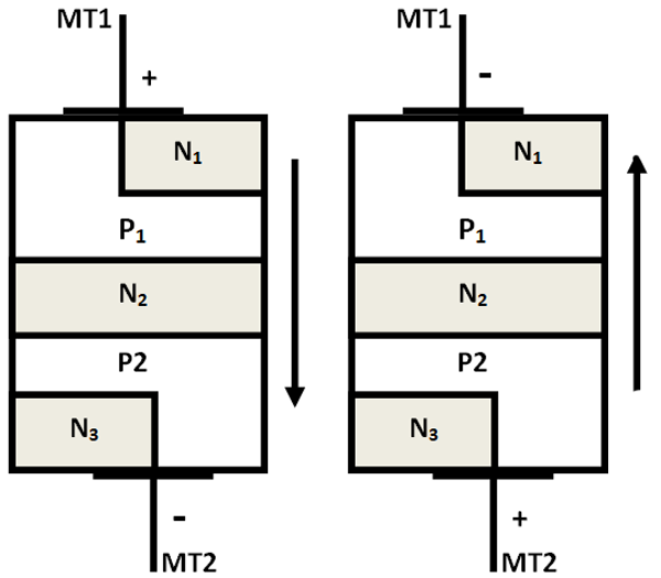
The above image shows the clear operation of the DIAC with respective to the polarities. Consider the MT1 terminal to be positive, then the P1 layer near MT1 will be activated, so the conduction will be taking place in the order of P1-N2-P2-N3. When the current is flowing from MT1 to MT2 the junction between P1-N2 and P2-N3 are Forward Biased and the junction between N2-P2 is reverse biased.
Similarly, if we consider MT2 terminal to be positive, then the P2 layer near MT2 will be activated and the conduction will be taking place in the order of P2-N2-P1-N1. The current will be flowing from MT2 to MT1 and the junctions between P2-N2 and P1-N1 are forward biased and the junction Between N2- P1 is reverse biased. Hence the conduction will be possible in both the directions.
VI Characteristics of DIAC
The V-I characteristic curve of the DIAC will be in the shape of a Z and the curve will be lying on the first and third quadrants because they conduct in both the positive and negative polarity. The First quadrant represents the positive half cycle where the current will be flowing from MT1 to MT2 and the second quadrant represents the negative half cycle where the current will be flowing from MT2 to MT1.
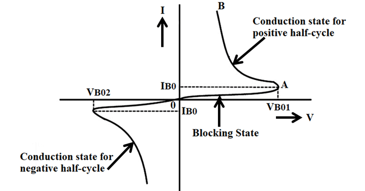
Initially, the resistance of the DIAC will be higher because of the Reverse Bias junction between the layers so there will be small leakage current flowing through the DIAC, it is mentioned as the blocking state in the curve. Once the applied voltage reaches the breakdown voltage the resistance of the DIAC drops abruptly and then it starts conducting which leads to a sharp decrease in voltage and the current starts increasing, which is mentioned as a conduction state in the curve. Most of the DIACs will be having the breakdown voltage around 30 Volts, the exact breakdown voltage will be based on the type of the device. The DIAC will be in the conducting state until the current reaches the particular value called the holding current, where holding current is the minimum current that required for a device to keep it in the ON state.
How to use a DIAC?
The DIACs are mostly used within the TRIAC circuits because the TRIAC does not fire a circuit symmetrically, due to the slight difference between the two halves of the device. The non- symmetrical firing and the resulting waveform will generate unwanted harmonics in the output, the lesser the symmetrical of the waveform the greater the harmonics will be.
The DIAC is connected in series with the gate of the TRIAC in order to resolve the problems caused due to the non-symmetrical firing. DIAC can help in switching symmetrically in both the halve cycle since it has a more even switching characteristics than the TRIAC. The DIAC can prevent any gate current flowing until the applied voltage reaches a certain voltage in any of the direction, hence the firing point of the TRIAC will be more even in both directions.
Applications of DIAC
If you want a TRIAC to conduct you need to provide a positive or negative pulse to the gate, in order to provide symmetric firing the DIAC are mostly used along with the TRIAC circuit. The DIACs are used for triggering TRIAC or other kinds of thyristors, apart from this they do not possess many applications. The DIACs are used as a trigger device in various applications such as Phase control circuits of motor speed control, light dimmers, heat controls, and many other control circuits. Let’s look into the examples of Light Dimmer and heat control circuits.
Heat Control:
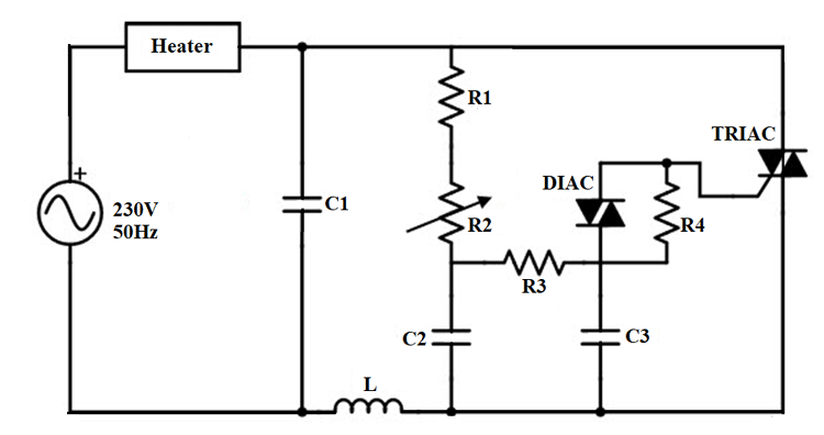
The Above circuit shows the typical structure of the DIAC-TRIAC combination used for smooth control of AC power to a Heater. The Capacitor C1 and The choke L form an LC circuit that slows down the voltage rise across the TRIAC when it is in OFF state. The R2 is the potentiometer that is used to control the applied voltage in both the half cycles and the resistor R4 across the DIAC ensures the Smooth control. The longer the TRIAC is conducting the larger the heat is dissipated from the heater, hence the DIAC here is used to deliver smooth control of the heat output from the heater.
Light Dimmer:
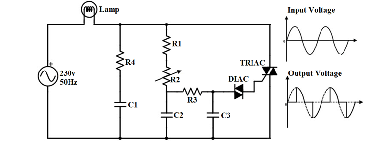
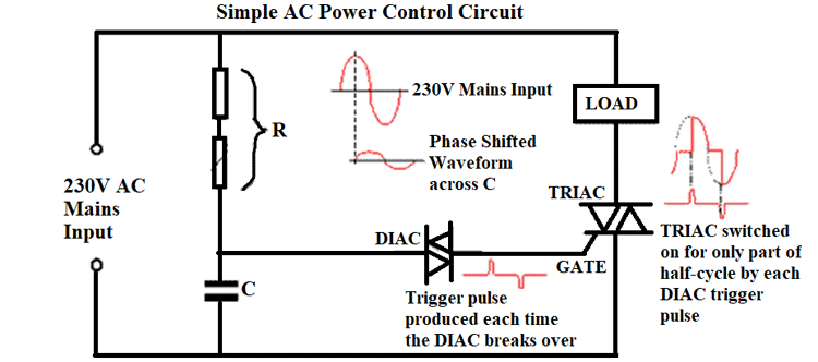
The Above circuit shows the RC phase shift network and DIAC controlled TRIAC for the light dimming application. The voltage applied to the gate terminal of the TRIAC is varied by the RC arrangement involving the Resistor R3 and the capacitor C3. When the device is in its OFF state the rate of voltage rise is limited by the series R4-C1 network that is connected across the TRIAC.
Once the input voltage is applied from the 230V power source the capacitors C1 and C2 start charging at the rate determined by the Variable resistor R2. Once the voltage across the capacitor C3 exceeds the breakdown voltage of the DIAC, it gets triggered and the DIAC starts conducting and this will discharge the capacitor C3 and the gate pulse is given to the TRIAC. The gate pulse turns ON the TRIAC and the current starts flowing through the lamp. By varying the Resistance in R2, the rate of charging of the capacitor also gets varied which in turn varies the voltage rate at which the TRIAC gets triggered in both the positive and negative half-cycles. The firing angle of the TRIAC can be varied up to 180 degrees so, the load voltage is co


