LP5907 250-mA, Low-Noise, High-PSRR, Ultra-Low-Dropout Voltage Regulator
The LP5907 is a low-nose, high PSSR, ultra-low dropout voltage regulator from TI. It is capable of delivering output current up to 250mA. The LP5907 also feature low quiescent current and low line and load transient response figures. All these feature makes the LP5907, the best candidate for RF and analog circuits. This device is available with fixed output voltages from 1.2 V to 4.5 V in 25-mV steps. Tiny packages make it easier to use with portable applications. The LP5907 is available in three different packages, 4 pin DSBGA, 5 pin SOT-23 and 4 pin X2SON.
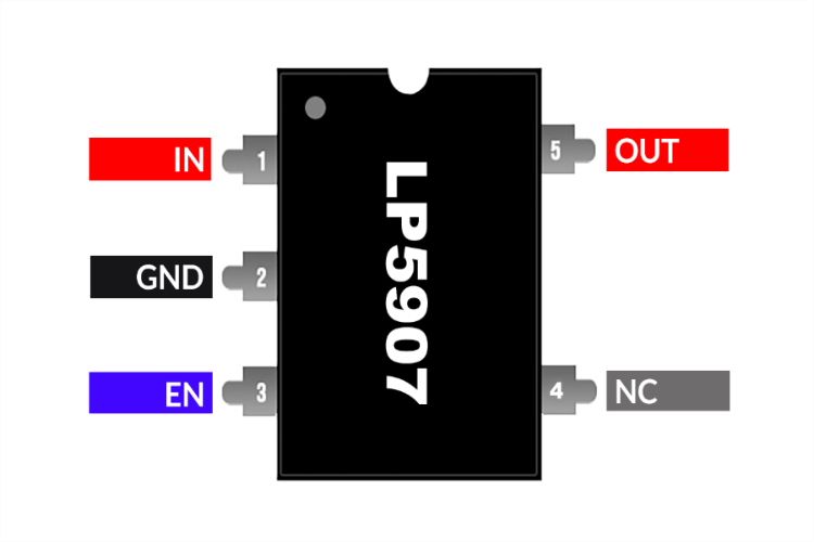
LP5907 Pinout Configuration
Here we have only included the pinout details for the SOT-23-5 package. You can get the pinout details of other packages from the datasheet attached to the end of this page.
| NAME | PIN | I/O | DESCRIPTION |
| IN | 1 | I | Input voltage supply. Connect a 1-µF capacitor at this input. |
| OUT | 5 | O | Regulated output voltage. Connect a minimum 1-µF low-ESR capacitor to this pin. Connect this output to the load circuit. An internal 230-Ω (typical) pulldown resistor prevents a charge remaining on VOUT when the regulator is in the shutdown mode). |
| EN | 3 | I | Enable input. A low voltage on this pin turns the regulator off and discharges the output pin to GND through an internal 230-Ω pulldown resistor. A high voltage on this pin enables the regulator output. This pin has an internal 1-MΩ pulldown resistor to hold the regulator off by default. |
| GND | 2 | - | Common ground |
| N/C | 4 | - | No internal electrical connection. |
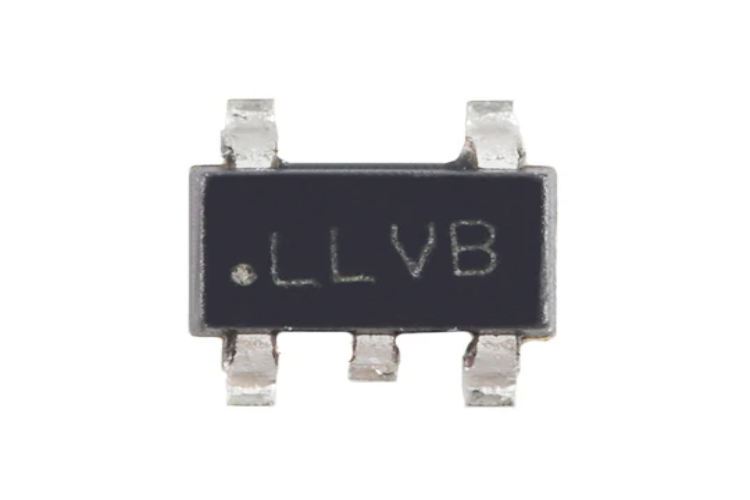
How to Identify LP5907 IC Variants
| Part Number | Package Type | Device Marking | Part Number | Package Type | Device Marking | |
| LP5907MFX-1.2/NOPB | SOT-23 | LLTB | LP5907SNX-4.0/NOPB | X2SON | GU | |
| LP5907MFX-1.5/NOPB | SOT-23 | LN8B | LP5907SNX-4.5/NOPB | X2SON | CO | |
| LP5907MFX-1.8/NOPB | SOT-23 | LLUB | LP5907UVE-1.2/NOPB | DSBGA | R | |
| LP5907MFX-2.5/NOPB | SOT-23 | LN7B | LP5907UVE-1.8/NOPB | DSBGA | S | |
| LP5907MFX-2.8/NOPB | SOT-23 | LLYB | LP5907UVE-2.8/NOPB | DSBGA | U | |
| LP5907MFX-2.85/NOPB | SOT-23 | LN4B | LP5907UVE-2.85/NOPB | DSBGA | V | |
| LP5907MFX-2.9/NOPB | SOT-23 | 1E5X | LP5907UVE-3.0/NOPB | DSBGA | B | |
| LP5907MFX-3.0/NOPB | SOT-23 | LLZB | LP5907UVE-3.1/NOPB | DSBGA | X | |
| LP5907MFX-3.1/NOPB | SOT-23 | LN5B | LP5907UVE-3.2/NOPB | DSBGA | C | |
| LP5907MFX-3.2/NOPB | SOT-23 | LN6B | LP5907UVE-3.3/NOPB | DSBGA | D | |
| LP5907MFX-3.3/NOPB | SOT-23 | LLVB | LP5907UVE-4.5/NOPB | DSBGA | Z | |
| LP5907MFX-4.5/NOPB | SOT-23 | LLXB | LP5907UVX-1.2/NOPB | DSBGA | R | |
| LP5907SNX-1.2/NOPB | X2SON | CF | LP5907UVX-1.8/NOPB | DSBGA | S | |
| LP5907SNX-1.8/NOPB | X2SON | CG | LP5907UVX-2.5/NOPB | DSBGA | E | |
| LP5907SNX-1.9 | X2SON | 3Z | LP5907UVX-2.8/NOPB | DSBGA | U | |
| LP5907SNX-2.2/NOPB | X2SON | EP | LP5907UVX-2.85/NOPB | DSBGA | V | |
| LP5907SNX-2.5/NOPB | X2SON | F9 | LP5907UVX-3.0/NOPB | DSBGA | B | |
| LP5907SNX-2.7/NOPB | X2SON | CH | LP5907UVX-3.1/NOPB | DSBGA | X | |
| LP5907SNX-2.75 | X2SON | HI | LP5907UVX-3.2/NOPB | DSBGA | C | |
| LP5907SNX-2.8/NOPB | X2SON | CI | LP5907UVX-3.3/NOPB | DSBGA | D | |
| LP5907SNX-2.85/NOPB | X2SON | CJ | LP5907UVX-4.5/NOPB | DSBGA | Z | |
| LP5907SNX-2.9/NOPB | X2SON | GV | LP5907UVX19/NOPB | DSBGA | 8 | |
| LP5907SNX-3.0/NOPB | X2SON | CK | LP5907UVX37/NOPB | DSBGA | 9 | |
| LP5907SNX-3.1/NOPB | X2SON | CL | LP5907YKGR-2.8 | DSBGA | 3 | |
| LP5907SNX-3.2/NOPB | X2SON | CM | LP5907YKGR-2.825 | DSBGA | 5 | |
| LP5907SNX-3.3/NOPB | X2SON | CN | LP5907YKGR-2.85 | DSBGA | P |
As mentioned earlier the LP5907 is available in a wide range of fixed output voltages. You can use the above table to identify the device using the markings on the device. For example, the device with the marking LLVB is the 3.3V version in SOT-23-5 package.
Features
- Input voltage range: 2.2 V to 5.5 V
- Output voltage range: 1.2 V to 4.5 V
- Stable with 1-µF ceramic input and output capacitors
- No noise bypass capacitor required.
- Remote output capacitor placement
- Thermal-overload and short-circuit protection.
- –40°C to 125°C operating junction temperature
- Low output voltage noise: < 6.5 µVRMS
- PSRR: 82 dB at 1 kHz
- Output voltage tolerance: ±2%
- Very low IQ (enabled): 12 µA.
- Low dropout: 120 mV (typical)
LP5907 Equivalents
AP2112, LD2985, TPS73633, TLV713, SGM2019
LP5907 Alternatives
LP2985, AMS1117, MIC5225, MIC5205, RT9193
Note: Complete technical details can be found in the LP5907 datasheet at this page’s end.
Application Circuit
The following image shows the typical application circuit for the LP5907.
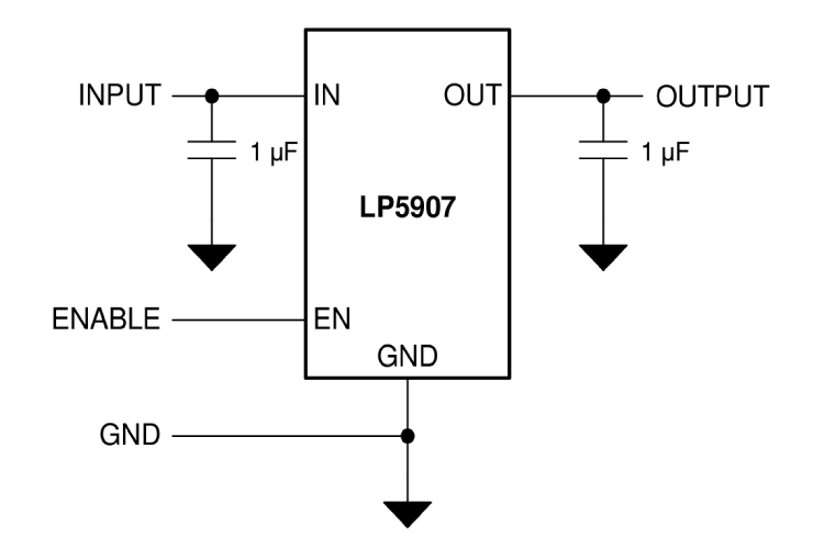
As you can see the circuit is very simple and only requires bare minimum components. 1Uf capacitors are used for input and output filtering. The device offers excellent noise performance without the need for a noise bypass capacitor and is stable with input and output capacitors with a value of 1µF.
Applications
- Smartphones
- Tablets
- Communications equipment
- Digital still cameras
- Factory automation
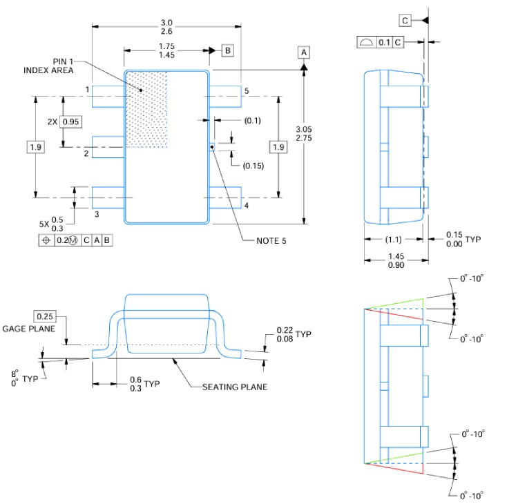
2D-Model and Dimensions
Below is the 2D CAD drawing of LP5907 (for the SOT-23-5 package) along with its dimensions in millimeters. The dimensions can be used to create custom footprints of the module and be used for PCB or CAD modelling.