LP2985 Low-Dropout Regulator
The LP2985 is a fixed output, low drop-out (LDO) regulator with output current capability of 150 mA, very low dropout voltage (280 mV), and better than 1.5 % Voltage Regulation Accuracy. LP2985 has an Enable pin to provide Zero-current shutdown mode. This voltage regulator comes with features, such as overcurrent and over-temperature protection.
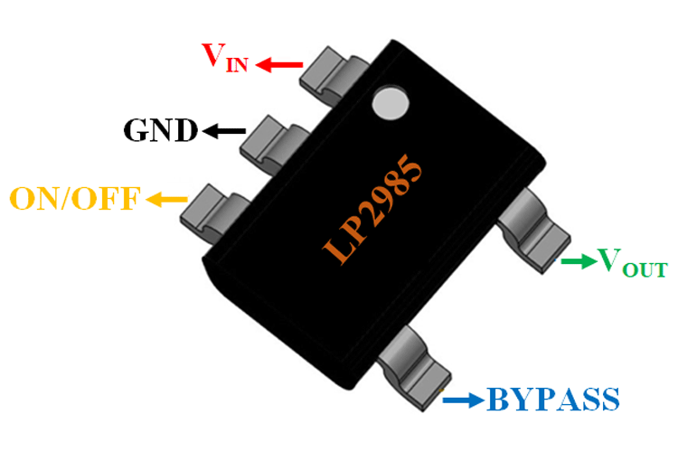
LP2985 LDO Pinout Configuration
|
Pin No. |
Pin Name |
Description |
|
1 |
VIN |
Supply Input |
|
2 |
GND |
Ground |
|
3 |
ON/OFF |
Active-low shutdown pin. Logic-high = enable, logic-low or open = shutdown |
|
4 |
BYP |
Reference Bypass: Connect external 470 pF capacitor to GND to reduce output noise. May be left open. |
|
5 |
OUT |
Regulator Output |
Features
- Input Supply Voltage: 2.2V to 16V
- Output Voltage: 3.3 V
- Output Current: 150mA
- Drop-out Voltage: 280 mV
- Voltage Regulation Accuracy: 1.5 %
- Operating Supply Current: 850 uA
- Line Regulation: 0.014 % / V
- Shutdown Current: 0.01 μA
- Overcurrent and Thermal Protection
- High Peak-Current Capability
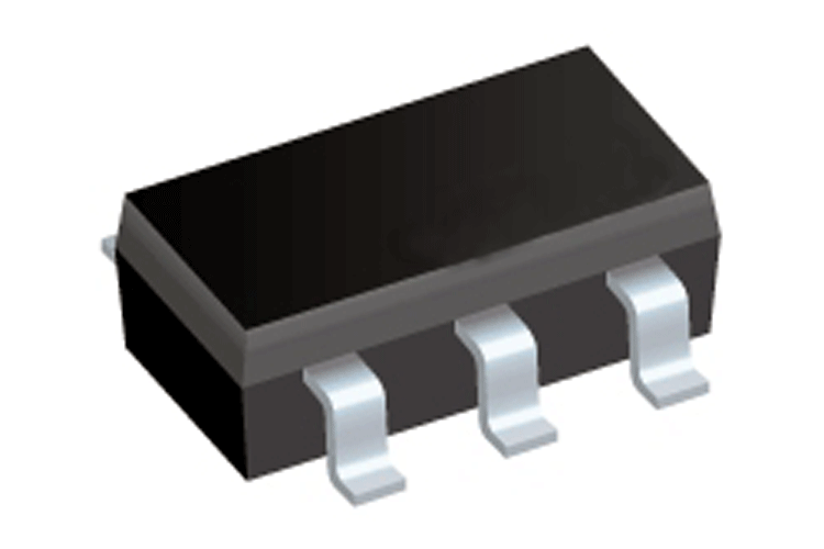
- Available in SOT-23-5 Package
Note: The Complete Technical Details can be found in the LP2985 datasheet given at the end of this page.
LP2985 Equivalents
MIC5205, TPS73633, TLV713
Alternative LDO Regulators
AP2112K, AMS1117, MIC5225
LP2985 Introduction
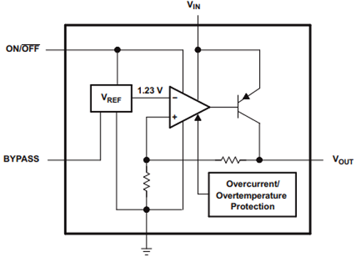
LP2985 is specially designed for Portable Devices, Digital Cameras, and MP3 players by Texas Instruments. The input voltage of the Regulator can be between 2.2V to 16V, the LP2985 includes a CMOS or TTL compatible enable/shutdown control input. When shutting down, power consumption drops nearly to zero. Output noise in LP2985 is further reduced by bypass pin. The functional block diagram of LP2985 is shown below. Main components of this regulator are the Reference voltage, Error amplifier, and Pass element (transistor).
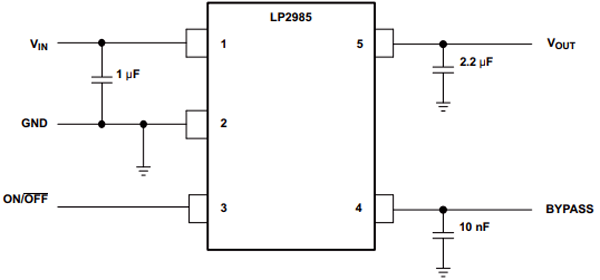
How to use the LP2985 LDO
LP2985 low dropout regulator comes in a 5-pin package. In LP2985 regulator, an extra bypass pin is introduced for further output noise reduction. This pin is connected to the ground through an optional 10nf capacitor. Vin pin is connected to the input power supply and a 1µf ceramic capacitor is used for input noise cancellation. The regulated voltage is obtained from the Vout pin. Enable pin can be used to turn on or off the regulator, this helps the designers to turn off the regulator and prevent battery usage when not in use. The application diagram for the LP2985 voltage regulator is shown below.
Applications
- Portable Devices
- Digital Cameras and Camcorders
- CD Players
- MP3 Players
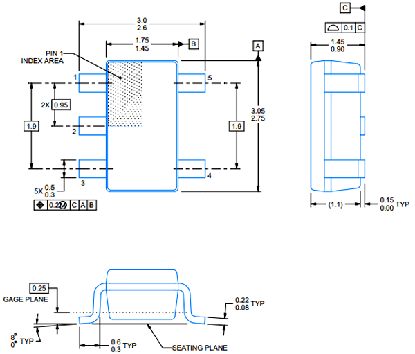
2D-Model of LP2985
Dimensions for the LP2985 Voltage Regulator is given below.