

Optimized with highly sensitive cap touch sensors, extensive peripheral circuits and 125℃ operation
Difference between Op-Amp and Comparator: Why Should You select a Comparator over an Op-Amp?
There are many reasons why you should not use an op-amp as a comparator, which is also the reason why dedicated comparator ICs exist. In this article, we will take a closer look at these reasons and also practically demonstrate the differences between op-amp and a comparator by comparing them against each other.
Reasons for Using Op-Amps as Comparators
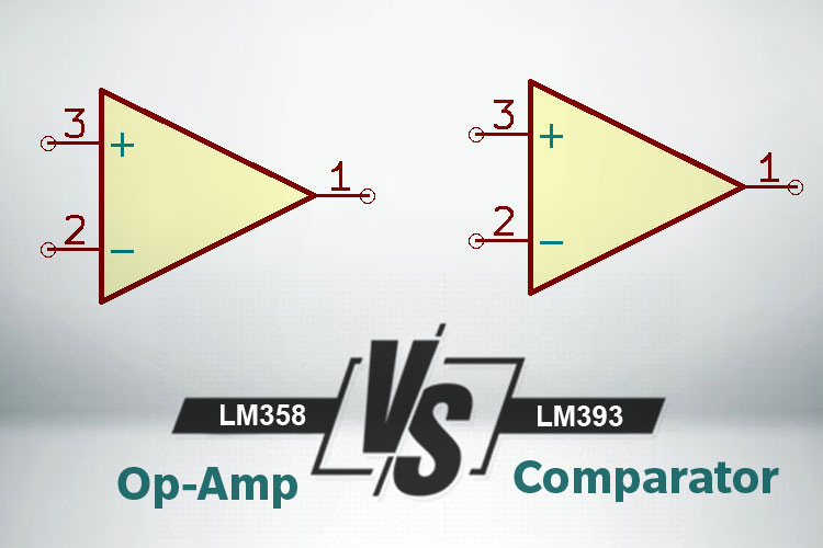
In general, op-amps and comparators come from the same family of high-gain differential amplifiers and share many common properties – differential input and a single-ended output that produces a voltage in response to a difference in input voltage. Even the schematic symbol for the two parts is the same, as shown in the figure below.
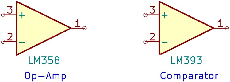
FIG.1 OP-AMP AND COMPARATOR SCHEMATIC SYMBOLS
One of the most common reasons to use op-amps as comparators is that the op-amps are available in packages that have two or even four op-amps. In cases like this, one or more of the op-amps might go unused, and instead of using a comparator somewhere else in the circuit, one of the op-amps could be used. For the most part, this is fine, but it can soon lead to problems if the differences in the way comparators and op-amps operate are not clearly understood.
Taking a Look inside Op-Amps and Comparators
The first step to understanding the differences between op-amps and comparators would be to take a look at the internal schematic. Here, the internal schematics of the LM358 op-amp and the LM393 comparator are shown. Because both parts are popular and easily available, they are also used in practical demonstration.
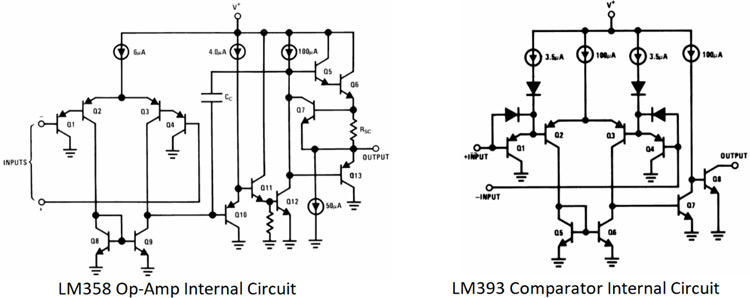
FIG.2 INTERNAL SCHEMATIC OF LM358 AND LM393
At first glance, the input stages look more or less the same (save the extra diodes on the comparator), with the only difference being the output stages.
Digital and Analog Outputs:
The biggest difference is that the comparator output is open-collector, and the op-amp output is a complementary NPN-PNP pair. This already points out the largest difference between the two – one of them is designed to provide digital outputs, and the other analog.
Since a comparator is essentially a 1-bit analog-to-digital converter, the digital output is designed to interface with a wide variety of logic families, each with different high and low threshold. An open-collector output can be part of a more complicated level-shifting circuit, to ensure that the digital input is being driven to the correct level. Another digital trick is to “wire-OR” multiple outputs – connecting them together to a single pull-up resistor, when any one of the comparators’ output is low, the overall output is low. This is useful in fault detection and window comparators, where the outputs of multiple comparators are tied together. This would not be possible with a complementary output stage. Another humorous anecdote is that while an op-amp can be used as a comparator, the comparator cannot be used as an op-amp – the output stage is simply not designed to operate at a voltage between the supply rails.
The output of the op-amp, however, is more complicated, because it is designed to replicate analog signals accurately with very low distortion.
Another point to note is that the output transistors of the op-amp are not power transistors and hence are not designed to operate saturated at one of the rails like a comparator. To keep the output saturated, the op-amp might draw more current than normal, which leads to heating. Driving the output transistors out of saturation can also take up more time thanks to storage charge in the base.
Comparator outputs, however, are designed to saturate cleanly to the rails, and sometimes even feature anti-saturation circuits. This might sound counterintuitive, but for power transistors with a rather large base-emitter capacitance, coming out of saturation might take some time. For this reason, some comparators feature circuits that operate their output transistors close to saturation, so they don’t take time to swing to the other rail. A good example of this is the LM311.
Compensation Capacitor (Cc):
The second big difference between the two circuits is the presence of “CC” in the op-amp circuit. This is the compensation capacitor that rolls off the gain of the op-amp at high frequencies. This is a necessary addition to an op-amp, where DC stability is important – there should not be oscillation on the output. This capacitor is also the main reason for the relative “slowness” of the op-amp – the compensation capacitor limits the output slew rate. This means that the op-amp takes a finite time to move its output between the supply rails. This (in combination with saturation issues) can lead to a significant delay in the response time of an op-amp used as a comparator.
The comparator, on the other hand, features no such limitations. Any small input difference causes the output to swing hard and fast to the supply rails, which is a good thing in digital systems where the speed is much appreciated.
Reversed Input pins:
A third and less noticeable difference is that the inverting and non-inverting inputs on the op-amp and comparator circuits are reversed (with respect to the current mirrors that act as active loads for the input transistors). This is because a comparator is designed to be stable in the open-loop configuration (or with positive feedback) and the op-amp is designed to have some form of negative feedback.
Input and Output Limitations on Op-Amp and Comparator
The differences in the internal circuits of op-amps and comparators represent the “microscopic” differences. There are other “macroscopic” differences that manifest themselves in the form of the input voltage range each type of device is rated to handle.
This has a lot to do with the type of feedback that an op-amp and comparator is designed to work with.
In the case of a comparator that can work open-loop or with positive feedback, the output must respond quickly if one of the inputs is higher or lower than the other by saturating at one of the rails, representing a digital 0 or 1.
An op-amp, on the other hand, that is designed to be used with an external negative feedback network, tries to keep both inputs the same by changing the output and hoping that the external network brings the input differential to zero.
The obvious takeaway from this is that comparators have a much larger input common-mode (and differential) voltage range than op-amps.
This is especially true at voltages near the supply rails, almost all op-amps operate with inputs (and outputs) to within a few volts or more of the supply rails (there exist rail-to-rail input and output op-amps, but they come with their own problems), and any excursion beyond these limits usually results in unwanted behavior:
1. Older op-amp types suffered from a problem called ‘phase reversal’, where driving the input beyond the common-mode range would lead to the output reversing in phase – basically inverting the output.
2. Input offset and input bias current are not constant over the input voltage range. This is a problem that manifests itself, especially in RRIO op-amps. Input overvoltage can sometimes activate the protective clamp diodes that shunt current to either of the supply rails. Some op-amps even have a pair of anti-parallel diodes across the two inputs, any large difference is immediately seen as a decrease in input impedance. This may or may not be a problem, depending on the input. While used in linear mode, these diodes are not a problem since negative feedback tries to keep the input differential zero. But when used open-loop with large input voltage swings, these diodes can go into conduction, decreasing input impedance and causing excessive heating and eventual destruction of the chip.
LM358 Op-Amp Vs LM393 Comparator - A Practical Example
The best way to compare the switching times of an op-amp and comparator is to set up a simple comparator circuit.
Here, an LM358 op-amp is set up as a comparator, and the LM393 is also set up as a comparator. The input is a square wave signal from A CMOS 555 timer, which provides fast edges. All chips are powered by a 5V supply.
For the first demonstration, the LM358 and LM393 are set up as non-inverting comparators, meaning that the output goes high when voltage on the non-inverting input exceeds the inverting input. Here, the inverting input is held at 2.5V, half the supply voltage.
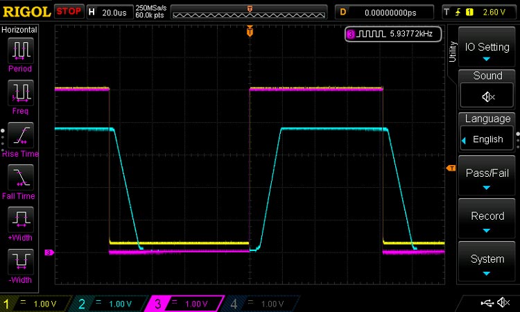
FIG.3 OUTPUT WAVEFORMS
Here, the pink waveform is the input, the yellow waveform is the output of the LM393, and the blue waveform is the output of the LM358.
It is clearly seen that the op-amp output shows all the characteristics described before: the response time is slow, the rising and falling edges are slew-rate limited, and the output voltage does not reach the positive supply. The yellow comparator output, on the other hand, is almost an exact replica of the fast input.
Whereas the response delay of the op-amp is close to 5us and the rise time is 15us, the comparator responds in 250ns and the rise time is less than 100ns.
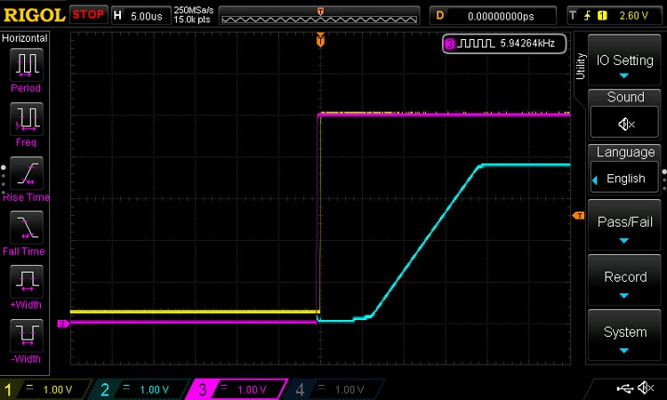
FIG.4 OP-AMP COMPARATOR TIMINGS
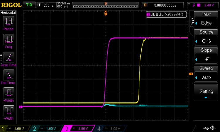
FIG.5 COMPARATOR TIMINGS
Conclusion
This article describes the differences between op-amps and comparators and why they are not always interchangeable. Care must be taken to ensure that the application part is thoroughly understood in order to ensure the best performance.


