PCR606 Logic Level Thyristor (SCR)

The PCR6060 is a Logic Level Thyristor which is commonly used with microcontrollers and other low voltage systems for switching applications. The Thyristor has an on-state current of 600mA with a reverse blocking voltage of 600V.
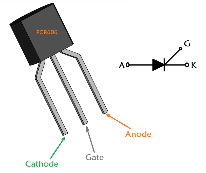
Pin Description
|
Pin Number |
Pin Name |
Description |
|
1 |
Anode |
Anode pin of the Thyristor , current flows in through Anode |
|
2 |
Cathode |
Cathode pin of the Thyristor, current exists through Cathode |
|
3 |
Gate |
Gate pin – used to turn on or off the Thyristor |
Features
- Logic Level Thyristor
- On-state current (IRMS) is 600mA
- Blocking Voltage (VDRM) is 600 V
- Gate Trigger Voltage (VGT) is 0.8V
- Holding current: 5mA
- Available in To-92 and SOT-23 Package
Note: Complete Technical Details can be found at the datasheet given at the end of this page.
Alternative for PCR606
BT169, PCR406
Other SCR (Thyristors)
2N2324, 2P4M, 2N1595, TYN612, PCR406
Brief Description of PCR606
The PCR606 is a logic level SCR, meaning it can be turned on or off directly with the I/O pins of microcontrollers or microprocessors without any driver circuit involved. This is because these types of SCR require very low gate voltage and gate current to turn them on. The PCR606 SCR can switch loads consuming upto 600mA, hence it is commonly used in the digital circuit to switch small loads like LED, Motors etc.
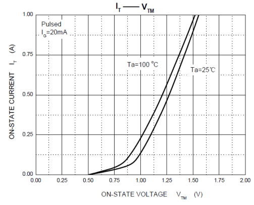
According to PCR606 datasheet, the required gate trigger voltage is only 0.8V and the gate current varies between 5uA to 120uA based on the part number of the SCR (refer datasheet below). As we know SCR is a current controlled device, hence the amount of current applied to gate depends on the voltage and current value that has to be switched. The below graph from datasheet can be used to determine the gate current.
How to Use PCR606 Thyristor?
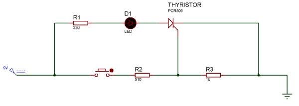
Initially, the switch S1 and S2 remains in normally-open state. When the supply ON, Thyristor remain reversed biased until the gate pulse provided. For providing gate pulse we have used Push Button S2. As the S2 switch close, thyristor turns ON and latch even we release the push button S2.
When the Thyristor has self-latched into the ON state, the only way to stop the Thyristor from conducting in this circuit is to interrupt the supply across the Thyristor. For that, we use switch S1, which short-circuit the anode and cathode, due to which the holding current get decreased to its threshold value. Therefore, Thyristor gets reset or turns OFF.
Resistance R1 used to provide sufficient gate current to turn ON the thyristor. Resistance R2 is used for decreasing the gate sensitivity and increase the dv/dt capability. Therefore, it prevents Thyristor from false triggering.
Applications
- Power Control
- Motor Control
- Heating
- Industrial and Domestic lighting
- Static Switching
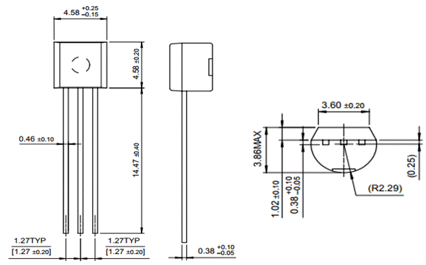
2D model of the component
If you are designing a PCD or Perf board with this component then the following picture from the Datasheet will be useful to know its package type and dimensions.