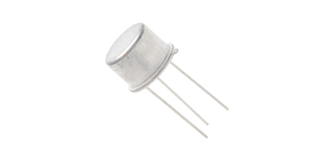
2N2324 Thyristor (SCR)
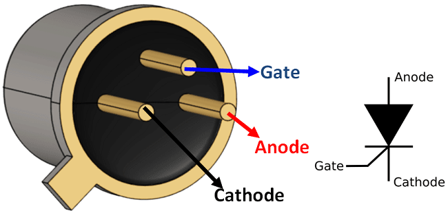
2N2324 SCR Pin Description
|
Pin Number |
Pin Name |
Description |
|
1 |
Cathode |
Cathode pin of Thyristor |
|
2 |
Gate |
Gate control pin of Thyristor |
|
3 |
Anode (case) |
Anode pin of Thyristor |
Note: The metal casing of the thyristor is conductive and acts as Anode.
Features and Specifications
- Solid State Thyristor – Silicon Controlled Rectifier (SCR)
- Forward Voltage: 100V
- On-State Current: 1.6A (RMS)
- Peak Surge current: 15A max
- Gate Voltage: 6V
- Gate threshold current: 200uA
- Available in To-39 Metal can Package
Alternatives Thyristors
TYN612, NTE5536, 2N650N, TYN608, S8016
Where to use 2N2324 Thyristor
The 2N2324 SCR is a power electronics switch. By default the switch is open and no current flows between the Anode and Cathode terminals of the SCR. When a small current is applied to the gate pin, the switch is closed and a large amount of current can be allowed to pass between the Anode and Cathode terminals.
This particular 2N23234 Thyristor can allow upto 100V and 1.5A current between the Anode and Cathode terminals and a gate voltage of 6V and current of 200uA is required to turn on the thyristor. So if you are looking for a current controlled switch of this specifications, then 2N2324 might be of interested to you.
How to use 2N2324 Thyristor
Using a Thyristor/SCR is very similar to that of a BJT (Transistor). The load to be switched is connected between the Anode and cathode and the Thyristor can be switched ON or OFF by applying a gate current to the gate pin of the Thyristors. A simpleThyristor circuit is shown below.
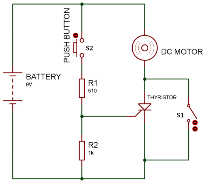
The Anode pin of the Thyristor is connected to the Load (Motor) and the Cathode pin is connected to the ground. The gate pin can be triggered by pressing the button S2, a potential divider is used to convert the 9V from battery into 6V, you can also use a microcontroller in place of the switch and potential divider network. When the switch S2 is not pressed the motor is in off state since gate pin is not energised this mode is called Forward blocking mode.
When the switch S2 is pressed the gate current is passed to the gate pin and the SCR begins to conduct and thus making the motor to rotate. This mode of SCR is called forward conduction mode. Now even after the Switch S2 is released the SCR will remain turned on, that is once the SCR is turned on it has to be turned off by using a different circuitry. This circuit is called as a commutation circuit. Here we have just used a switch S1 across the SCR, when this switch is closed the entire current through SCR will flow through the switch and hence the minimum current required to keep the SCR ON a.k.a Holding current is lost and hence the SCR is turned OFF.
Applications
- Power electronic switching devices
- Motor controllers
- Over Voltage protection circuits
- Electronic Fuse circuits
- High current protection circuits
- Surge protection circuits
- Inverters/Converter circuits
2D-Model and Dimensions


