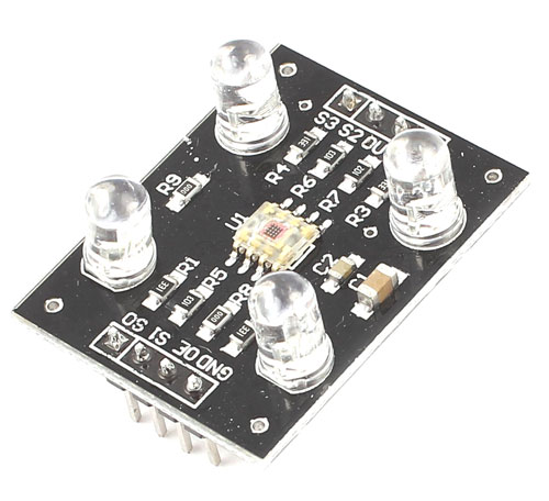
TCS3200 Color Sensor Module
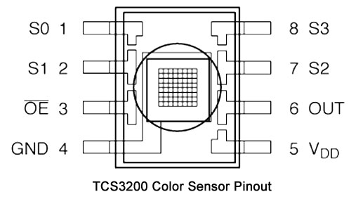
TCS3200 Pin Configuration
|
PIN NAME |
PIN NUMBER |
DESCRIPTION |
|
GND |
4 |
Power supply ground. All voltages are reference to the ground. |
|
VCC |
5 |
Supply voltage |
|
OE |
3 |
Enable for FO (Active low) |
|
OUT |
6 |
Output frequency (fo) |
|
S0, S1 |
1, 2 |
Select lines for output frequency scaling |
|
S2, S3 |
7,8 |
Select lines for photodiode type. |
|
S0 |
S1 |
OUTPUT FREQUENCY SCALING(f0) |
|
L |
L |
Power down |
|
L |
H |
2% |
|
H |
L |
20% |
|
H |
H |
100% |
|
S2 |
S3 |
PHOTODIODE TYPE |
|
L |
L |
RED |
|
L |
H |
BLUE |
|
H |
L |
CLEAR (NO FILTER) |
|
H |
H |
GREEN |
The sensor has four different types of filter covered diodes. In the 8 x 8 array of photodiodes, 16 photodiodes have Red filters, 16 have Blue filters, 16 have Green filters and the rest 16 photodiodes are clear with no filters. Each type can be activated using the S2, S3 selection inputs. Since each photodiodes are coated with different filters each of them can detect the corresponding colours. For example, when choosing the red filter, only red incident light can get through, blue and green will be prevented. By measuring the frequency, we get the red light intensity. Similarly, when choose other filters, we can get blue or green light.
We can also set the frequency scaling option by using the S0, S1 select lines. Normally, in Arduino 20% frequency scaling is used.
Brief Description
This Arduino compatible TCS3200 color sensor module consist of a TAOS TCS3200 RGB sensor chip and 4 white LEDs. The main part of the module is the TCS3200 chip which is a Color Light-to-Frequency Converter. The white LEDs are used for providing proper lighting for the sensor to detect the object colour correctly. This chip can sense a wide variety of colours and it gives the output in the form of corresponding frequency. This module can be used for making colour sorting robots, test strip reading, colour matching tests, etc.
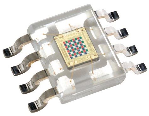
The TCS3200 chip consist of an 8 x 8 array of photodiodes. Each photodiode have either a red, green, or blue filter, or no filter. The filters of each color are distributed evenly throughout the array to eliminate location bias among the colors. Internal circuits includes an oscillator which produces a square-wave output whose frequency is proportional to the intensity of the chosen color.
Features and Specifications
- Input voltage: (2.7V to 5.5V)
- Interface: Digital TTL
- High-resolution conversion of light intensity to frequency
- Programmable colour and full-scale output frequency
- No need of ADC(Can be directly connected to the digital pins of the microcontroller)
- Power down feature
- Working temperature: -40oC to 85oC
- Size: 28.4x28.4mm(1.12x1.12")
Note: Complete technical information can be found in the TCS3200 Datasheet, linked at the bottom of this page.
How to use the Module Pin Configuration
TCS3200 color sensor module can be used to detect the colours with the help of a microcontroller. Actually, the microcontroller is measuring the output frequency from the 6th pin.
To determine the color of an object, we’ve to measure the frequency from 6th pin when each filter is activated.
Set both S2 and S3 to LOW, measure the frequency. Now we get the intensity of RED component in the object.
Set S2 to LOW and S3 to HIGH in order to get the intensity of BLUE component in the object.
Set both S2 and S3 to HIGH and get the intensity of GREEN component in the object.
Compare the frequencies of the three components to get the actual colour of the object.
TIP: In Arduino, we can use the ‘pulseIn’ command to get the frequency variations.
e.g.:
digitalWrite(S2, LOW);
digitalWrite(S3, LOW);   //Activating photodiode with red filter
red = pulseIn(outpin, LOW);
Here we get the value corresponding to the red color component of the object color.
Similarly, we’ve to activate each photodiodes by changing the S2 and S3 states and read the corresponding values of green and blue colour components of the object colour.
For a Red object, we get an approximate value of red=16, green=53 and blue=45. This may vary from ambient light and experiment setup. For good results, it’s better to cover the object and sensor from ambient light.
Programming Logic
- First set the input pins as input and output pins as output. No need to use analog pins.
- Set S0 and S1 to high or low to set desired frequency scaling.
- In loop, activate each filters by setting S2 and S3 to HIGH or LOW and measure frequency ‘fo’ from 6th pin to get corresponding colour intensity. Compare frequencies of each colour to determine the colour of the object.


