Photodiode
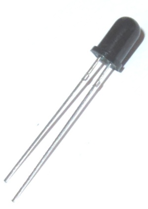
What is Photodiode? Photodiodes, as the name suggest, are just another type of diodes having an anode and cathode similar to normal LEDs. But, unlike LEDs they do not emit light. Instead, when they detect light they allow some current to flow through it, and the amount of current that flows through the Photodiode is directly proportional to the amount of light detected by the Photodiode. It makes it suitable to use along with the IR LEDs in IR sensor modules.
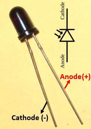
Photodiode Pinout Configuration
|
No: |
Pin Name |
Identification |
Description |
|
1 |
Anode |
The longer lead |
This is the positive (+) pin of the IR diode. But inversely connected to ground during usage |
|
2 |
Cathode |
The shorter lead |
This is the negative (ground) pin of the IR diode. But inversely connected to supply voltage during usage |
Photodiode Specifications
- Wavelength Sensitivity (λP): 940nm
- Open Circuit Voltage: 0.39V
- Reverse breakdown voltage: 32V
- Reverse Light current: 40μA
- Reverse Dark current: 5nA
- Rise Time/ Fall Time: 45/45nS
- View Angle: 80 deg
- Package: 5mm
Note: Read the article further and check the photodiode datasheet attached at the end of the article to learn why these parameters are important.
Alternatives light detectors
IR receivers (TSOP), Phototransistor, LDR, Photocells, Solar panels
Where to use photodiodes
When photodiodes detect light they allow some current to flow through it and the amount of current is directly proportional to the amount of the light detected by the Photodiode. Due to this property of Photodiode, it is fairly used in situations where light has to be detected. It is also commonly used with IR transmitter (IR LED) to form an IR pair and used in applications like object detection, counter, encoder and much more. So if you are looking for a pair to use with your IR LED or just trying to detect light for your project then this photodiode might be the right choice for you.
How to use a Photodiode
When it comes to using a Photodiode, one important thing to remember is that Photodiode should always be connected in reverse polarity. That is the Anode will be connected towards the ground and the cathode will be connected to supply voltage. When connected in this way (shown in the circuit below) the photodiode will start conducting some current based on the light sensed by it. The maximum current that could flow during full light condition is 40μA. Even when the photodiode is placed in the dark environment it consumes some current which is equal to 5nA.
Normally a photodiode will be used as a potential divider here I have used a 10K resistor to form the divider as shown below
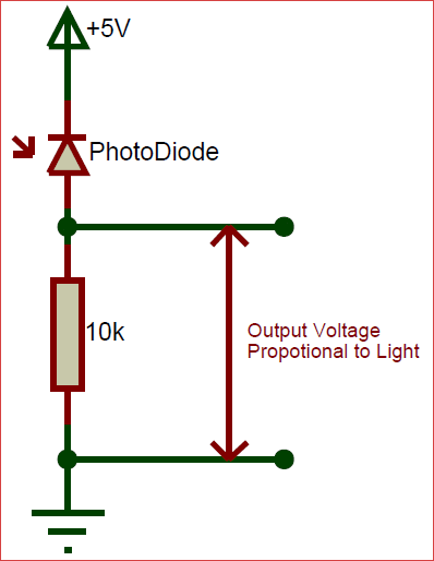
When the light falls on the Photodiode as said earlier a current will flow through it. This current will create a voltage drop across the photodiode and also across the 10K resistor since they form a voltage divider. Then this output voltage can be used to predict the light by reading the voltage through a microcontroller or by using Op-Amps in comparator mode. There are also many other circuits in which you can use a photodiode. This was explained for its simplicity so go ahead and try your own fun circuits
Applications
- Used to detect Light and its intensity
- Used with IR LED for object detection, counting, encoder and more
- Used in line follower and object avoiding robot
- Can also be used to detect fire with proper tuning
- Distinguish between Day and night
- Automatic light (streetlight or vehicle light) control
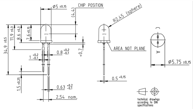
2D model of Photodiode (5mm)