Voltage Sensor Module
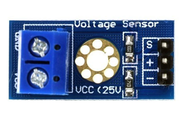
Voltage Sensor is a precise low-cost sensor for measuring voltage. It is based on the principle of resistive voltage divider design. It can make the red terminal connector input voltage to 5 times smaller.
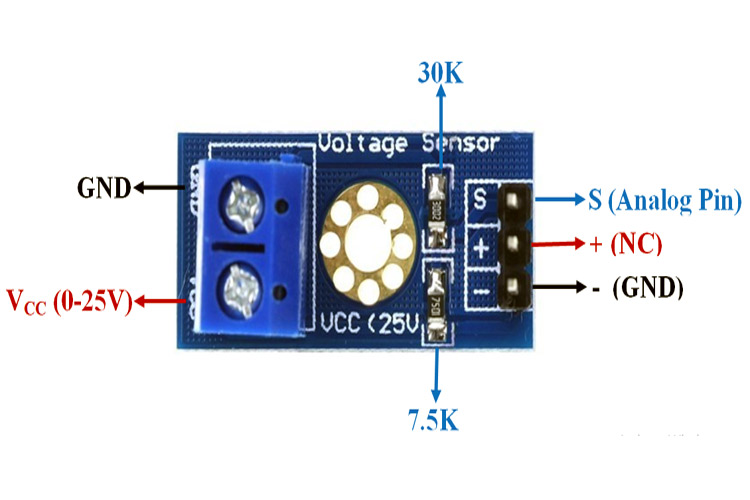
Voltage Sensor Module Pinout Configuration
|
Pin Name |
Description |
|
VCC |
Positive terminal of the External voltage source (0-25V) |
|
GND |
Negative terminal of the External voltage source |
|
S |
Analog pin connected to Analog pin of Arduino |
|
+ |
Not Connected |
|
- |
Ground Pin connected to GND of Arduino |
Voltage Detection Sensor Module Features & Specifications
- Input Voltage: 0 to 25V
- Voltage Detection Range: 0.02445 to 25
- Analog Voltage Resolution: 0.00489V
- Needs no external components
- Easy to use with Microcontrollers
- Small, cheap and easily available
- Dimensions: 4 × 3 × 2 cm
Other Modules: IR Sensor Module, LDR Sensor Module, TP4056A Li-ion Battery Charging/Discharging Module, DS3231 RTC Module, TMC2209 Stepper Motor Driver Module, DRV8825 Stepper Motor Driver Module, A4988 Stepper Motor Driver Module, NEO-6MV2 GPS Module, Joystick Module, EM18 - RFID Reader Module, ADXL335 Accelerometer Module, Soil Moisture Sensor
Related Components: HMC5883L, Resistors, Voltage Regulator IC
Brief about Voltage Sensor Module
Voltage Detection Sensor Module is a simple and very useful module that uses a potential divider to reduce any input voltage by a factor of 5. This allows us to use the Analog input pin of a microcontroller to monitor voltages higher than it capable of sensing. For example, with a 0V - 5V Analog input range, you are able to measure a voltage up to 25V. This module also includes convenient screw terminals for easy and secure connections of a wire.
The internal circuit diagram of the Voltage Sensor Module is given below.
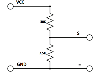
The voltage circuit consists of a voltage divider circuit of two resistors in which R1 is 30K and R2 is 7.5K.
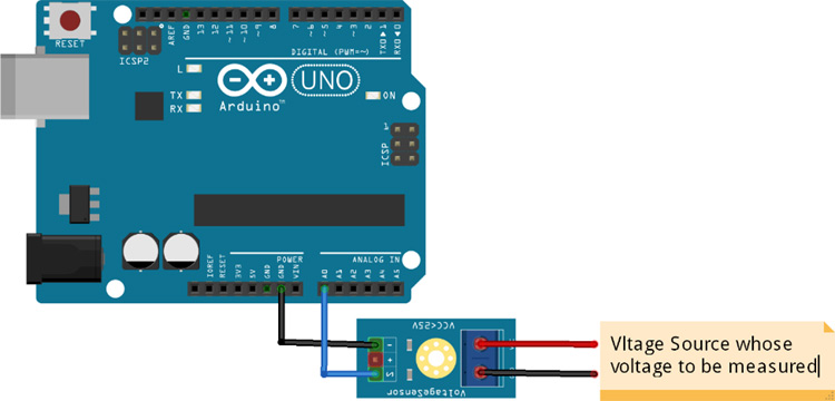
How to Use Voltage Sensor Module with Arduino
Interfacing a voltage sensor with Arduino or any other microcontroller is pretty straight forward. Connect the VCC and GND of voltage source whose voltage to be measured to the screw terminals of the voltage sensor. Connect the S and – (GND) pins of voltage sensor to Analog pin and GND of Arduino respectively.
Input and output voltage can be calculated using:
Vin = Vout * (R2/(R1+R2))
Here R1 = 30K ohm and R2 = 7.5K ohm
Vout = (analogvalue * 5 / 1024).