DRV8825 Stepper Motor Driver Module
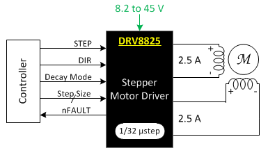
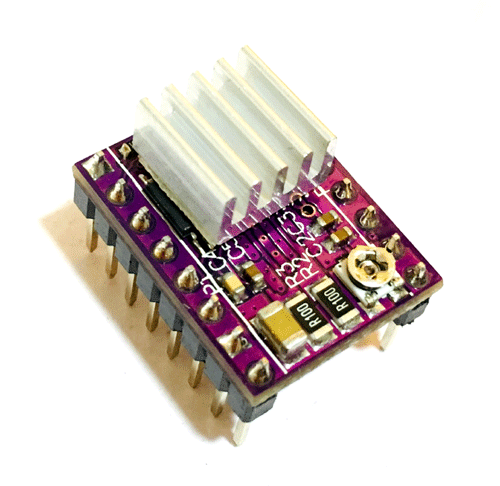
The DRV8825 is a Motor Driver with two H-bridge drivers and a microstepping indexer. The driver has a maximum output capacity of 45 V and ± 2.5 A. It can operate bipolar stepper motors in full, 1/2, 1/4, 1/8, 1/16 and 1/32-step modes. This driver module is generally used in Robotics, ATMs and Gaming Machines.
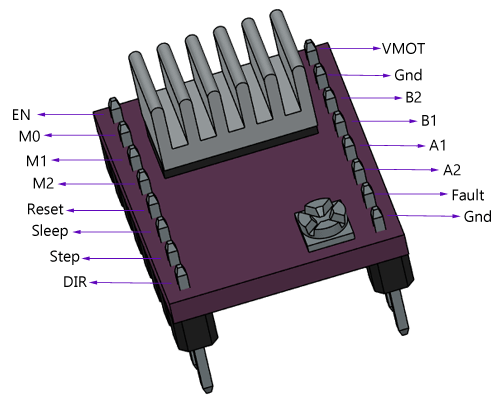
Pin Configuration
|
Pin Name |
Description |
|
VDD & GND |
Connected to 5V and GND of Controller |
|
VMOT & GND MOT |
Used to power the motor |
|
B1, B2 & A1, A2 |
Output Pins, Connected to the 4 Wires of motor |
|
DIRECTION |
Motor Direction Control pin |
|
STEP |
Steps Control Pin |
|
M0, M1, M2 |
Microstep Selection Pins |
|
FAULT |
Fault Detection Pin |
|
SLEEP |
Pins For Controlling Power States |
|
RESET |
|
|
ENABLE |
DRV8825 Stepper Driver Module Specification
- Max. Operating Voltage: 45 V
- Min. Operating Voltage: 8.2 V
- Max. Current Per Phase: 2.5 A
- PCB Size: 15 mm x 20 mm
Features
- Six step resolution: Full step, ½ step, ¼ step, 1/8, 1/16 and 1/32 step
- Adjustable output current via potentiometer
- Automatic current decay mode detection
- Over temperature shutdown circuit
- Under-voltage lock out
- Over current shutdown
Alternatives for DRV8825: A4988, A498, L6474, L6207, L6208, TMC2208, TMC2209
Note: Complete Technical Details can be found at the DRV8825 datasheet given at the end of this page.
How to Use DRV8825 Driver Module
Interfacing diagram for DRV8825 is shown below. Using DRV8825 you can control the stepper motor using very few pins. The module has a pinout and interface that are nearly identical to those of the A4988 stepper motor driver carrier.

As shown in the above diagram, DIR, STEP and FAULT pins of the module are connected with microcontroller to drive the stepper motor. STEP pin used to control the steps while DIR pin is used to control direction. The DRV8825 also features a FAULT pin, Fault pin is shorted to SLEEP pin so, whenever the Fault pin is driven LOW, the whole chip is disabled. Microstep pins (M0, M1 and M2) are used to operate the driver module in different step functions. In the above circuit M0, M1, and M2 pins left disconnected, that means the driver will operate in full-step mode. DRV8825 has low-ESR ceramic capacitors onboard, which makes it vulnerable to voltage spikes. So it is recommended to put an at least 47µf capacitor across the motor power supply pins. It is commonly used in controlling the NEMA series stepper motors like NEMA17, NEMA23, NEMA34
Applications
- Automatic Teller Machines
- Money Handling Machines
- Video Security Cameras
- Printers
- Scanners
- Office Automation Machines
- Gaming Machines
- Factory Automation
- Robotics
- .
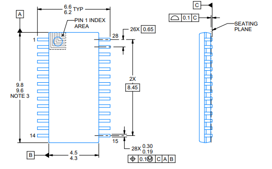
DRV8825 IC 2D-Model


