Optimized at frequencies beyond traditional industry targets to support emerging applications
Introduction to Gas Sensors: Construction Types and Working
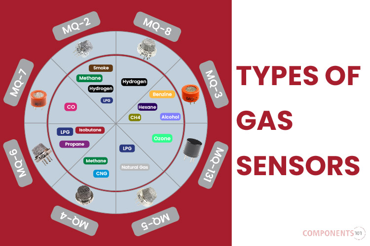
A Typical human nose has 400 types of scent receptors enabling us to smell about 1 trillion different odors. But still, many of us do not have the capacity to identify the type or concentration of gas present in our atmosphere. This is where Sensors come in, there are many types of sensors to measure different parameters and a Gas sensor is one which comes in handy in applications where we have to detect the variation in the concentration of toxic gases in order to maintain the system safe and avoid/caution any unexpected threats. There are various gas sensors to detect gases like oxygen, Carbon Dioxide, Nitrogen, methane etc. They can also be commonly found in devices that are used to detect the leakage of harmful gases, monitor the air quality in industries and offices etc.
In this article, we will learn more about gas sensors, their construction, types, working and how they can be used to measure the required type and concentration of Gas in our atmosphere. There are many types of Gas sensors, but the MQ-type gas sensors are commonly used and widely popular so will focus more on these types of sensors for this article.
What is a gas sensor?
A gas sensor is a device which detects the presence or concentration of gases in the atmosphere. Based on the concentration of the gas the sensor produces a corresponding potential difference by changing the resistance of the material inside the sensor, which can be measured as output voltage. Based on this voltage value the type and concentration of the gas can be estimated.
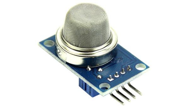
The type of gas the sensor can detect depends on the sensing material present inside the sensor. Normally these sensors are available as modules with comparators as shown above. These comparators can be set for a particular threshold value of gas concentration. When the concentration of the gas exceeds this threshold the digital pin goes high. The analog pin can be used to measure the concentration of the gas.
Types of Gas Sensors Based on Working Principles
There are many types of gas sensors and there are different ways to classify them. The main classification of the gas sensors can be done based on the working principle. Here are some of the major classifications of gas sensors based on their working principle.
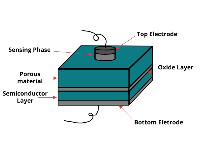
Semiconductor / Metal Oxide-based Gas Sensors operate by detecting changes in the resistance of a semiconductor material when exposed to gases. These sensors typically consist of a sensing element made from metal oxides such as tin dioxide (SnO2), integrated onto a substrate with electrodes and a heater. The metal oxide layer is porous to increase the surface area for gas interaction. When gases adsorb onto the metal oxide surface, the sensor's electrical conductivity changes, altering its resistance. These sensors are highly sensitive to a broad range of gases and are relatively inexpensive to produce. However, they are susceptible to environmental variables like temperature and humidity and require regular calibration, reducing their lifespan.
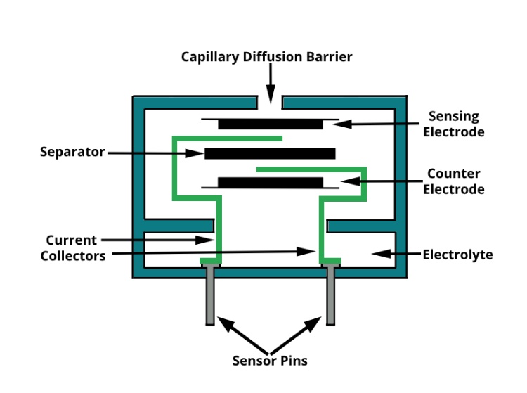
Electrochemical Gas Sensors measure gas concentrations by oxidizing or reducing the gas at an electrode and measuring the resultant current. Electrochemical gas sensors are composed of electrodes (working, counter, and reference) immersed in an electrolyte, usually housed in a compact casing with a gas-permeable membrane. Target gases diffuse through the membrane and undergo a redox reaction at the working electrode, generating a current proportional to the gas concentration. They are known for their high specificity and accuracy and have low power requirements. The main drawbacks include potential poisoning by other gases and a limited lifespan due to the consumption of active materials.
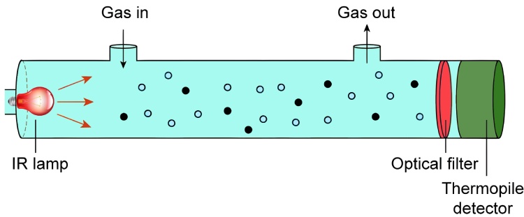
Non-Dispersive Infrared (NDIR) Gas Sensors use an infrared light source and an infrared detector to measure gas concentration based on infrared absorption. NDIR gas sensors consist of an infrared light source, a gas sample chamber, a wavelength filter, and an infrared detector. The gas chamber is designed to optimise the path length for accurate detection. Gases absorb specific wavelengths of infrared light; the amount of absorbed light is measured by the detector to determine gas concentration. These sensors are highly accurate, have a long operational life, and are immune to sensor poisoning, but they are more expensive and can only detect gases that absorb infrared light.
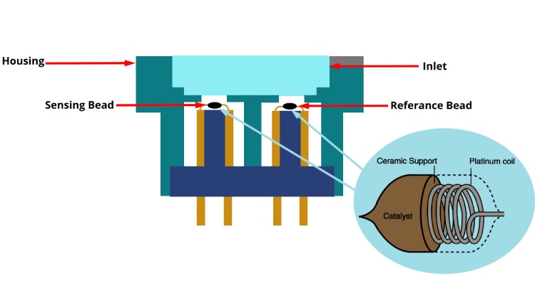
Catalytic Gas Sensors detect flammable gases using a catalytic bead that changes resistance when it oxidizes the gas. Catalytic gas sensors feature a catalyst-coated sensing element (often platinum) and a reference element, both part of a Wheatstone bridge circuit, housed in a robust casing to withstand harsh environments. When combustible gases oxidise on the catalyst surface, heat is generated, causing a change in resistance that is measured by the circuit. These sensors are effective at detecting low gas concentrations and have a quick response time. However, they require oxygen to function and can be poisoned by certain chemicals.
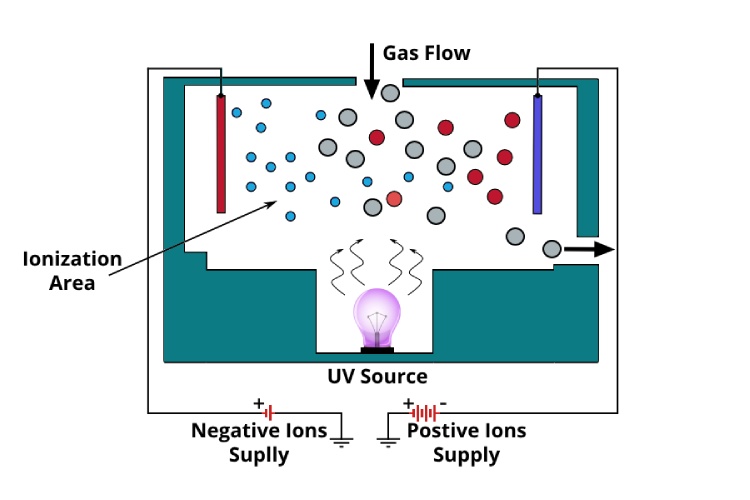
Photoionisation Detectors (PIDs) utilize ultraviolet light to ionize gases, measuring the current generated by these ions to determine gas concentration. PIDs consist of an ultraviolet (UV) lamp, an ionisation chamber, and electrodes for measuring the ion current. The UV lamp ionises gas molecules within the chamber. Ionised gas molecules generate an electrical current between the electrodes, which is proportional to the concentration of VOCs. PIDs are particularly sensitive to volatile organic compounds and respond quickly. Their main disadvantages are the high cost of lamp replacement and sensitivity to environmental factors like humidity and temperature.
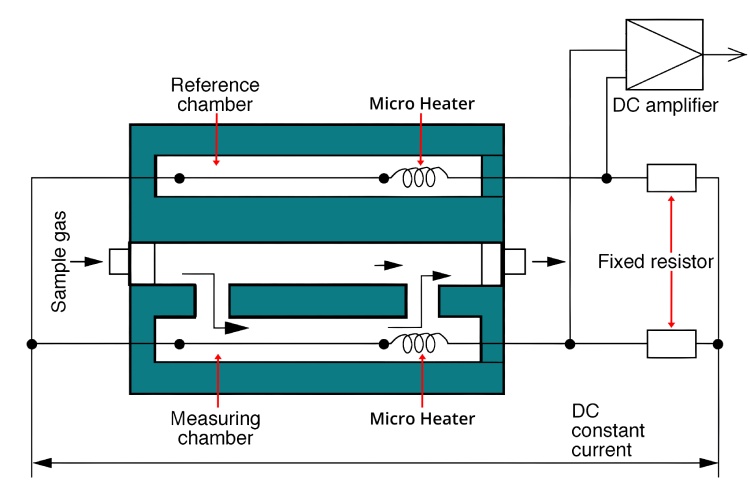
Thermal Conductivity Gas Sensors assess changes in thermal conductivity caused by different gases in the surrounding environment. Thermal conductivity gas sensors typically consist of a pair of thermistors or thermal conductors placed in a bridge circuit, with one exposed to the target gas and the other to a reference gas. The presence of gas changes the thermal conductivity around the sensing element, altering the temperature and thus the resistance, which is measured by the circuit. While they can detect a wide array of gases and are simple and durable, their sensitivity is lower compared to other types of sensors, and they are influenced by ambient temperature.
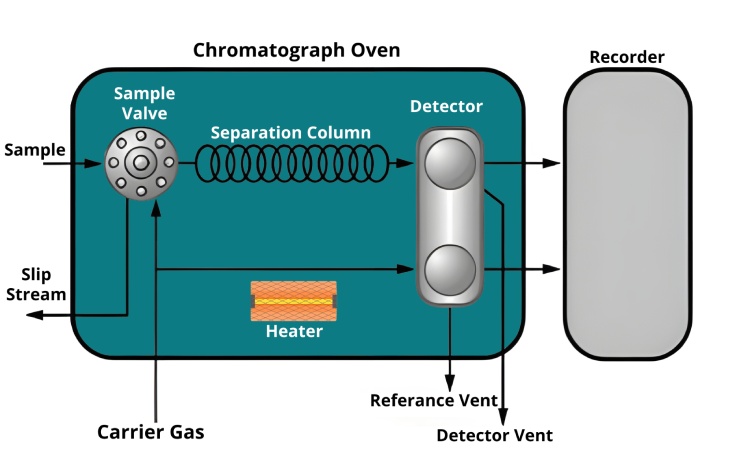
Gas Chromatograph Analyzers separate components of a gas mixture and measure each component using various detectors. Gas chromatograph analysers comprise an injector, a chromatographic column, a carrier gas system, and a detector, all housed in a controlled environment. Gas samples are injected into the column, separated based on their interactions with the column material, and then detected and quantified by the detector. This method is highly accurate and can detect very low concentrations of gases, capable of analyzing complex mixtures. However, these analyzers are expensive, require skilled operation, and are bulkier than other types of gas sensors.
Capacitance-based Gas Sensors detect changes in the capacitance caused by the dielectric constant changes of a gas absorbed on the sensor's coating. Capacitance-based gas sensors consist of a capacitor with a dielectric material that interacts with the target gas, often built on a microelectromechanical system (MEMS) platform for miniaturization. The adsorption of gas molecules changes the dielectric constant of the material, altering the capacitance, which is then measured. While these sensors are particularly sensitive to changes in humidity and useful in moisture detection applications, they are also susceptible to other environmental factors like temperature, often requiring careful calibration.
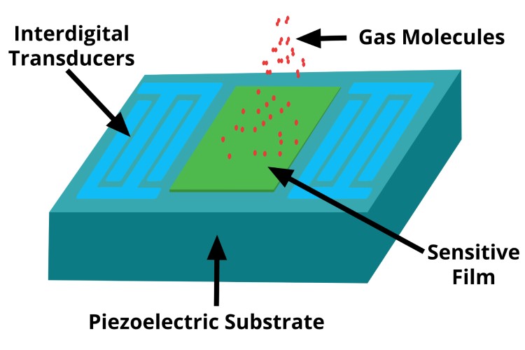
Acoustic-based Gas Sensors use the principle that the speed of sound in a gas mixture varies with its composition. These types of sensors include a sound wave emitter and receiver, with a chamber or path for the gas to interact with the sound waves. Changes in acoustic properties, such as speed or attenuation of sound waves, caused by the presence of gas are measured and analyzed. These sensors are non-invasive and quick to detect changes, although they may struggle with accuracy and require frequent calibration to account for environmental conditions like temperature and pressure.
Calorimetric Gas Sensors work by measuring the heat change caused by a chemical reaction between the target gas and a reagent. Calorimetric gas sensors feature a reaction chamber with a catalyst or reagent that reacts with the target gas, producing heat. This chamber is coupled with a temperature sensor. The heat released or absorbed during the gas reaction changes the temperature, which is detected by the temperature sensor. This change in temperature affects the sensor's properties, such as electrical resistance or thermoelectric voltage. These sensors are effective for specific gases but generally have a slower response time and may offer lower sensitivity compared to other types.
Magnetic Gas Sensors leverage the magnetic properties of certain gases, such as oxygen, to gauge gas concentration. Magnetic gas sensors comprise a magnetic material whose properties change in the presence of certain gases, integrated with a magnetic field sensor to detect these changes. The interaction of target gases with the magnetic material alters its magnetic properties, which are then detected and measured. They are highly stable and unaffected by most interference gases but are limited to detecting paramagnetic gases and are generally more complex and costly.
Semiconductor / Metal Oxide-based Gas Sensor Construction
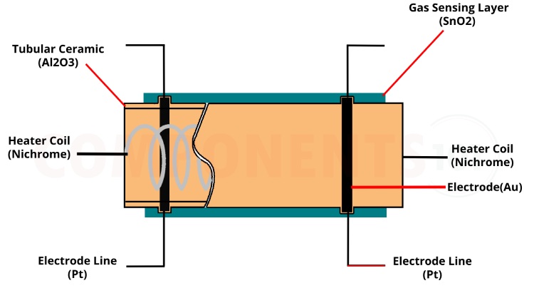
Of all the above-listed types, the most commonly used gas sensor is the Semiconductor/ Metal oxide semiconductor-based gas sensor. All Gas sensors will consist of a sensing element which comprises of the following parts.
- Gas sensing layer
- Heater Coil
- Electrode line
- Tubular ceramic
- Electrode
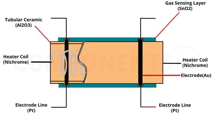
The below image illustrates the parts present in a metal oxide gas sensor
And here is an actual such senor with its protective cover removed.
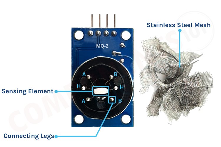
The purpose of each of these elements is as below:
Gas sensing layer: It is the main component in the sensor which can be used to sense the variation in the concentration of the gases and generate the change in electrical resistance. The gas sensing layer is basically a chemiresistor which changes its resistance value based on the concentration of a particular gas in the environment. Here the sensing element is made up of a Tin Dioxide (SnO2) which, in general, has excess electrons (donor element). So whenever toxic gases are being detected the resistance of the element changes and the current flown through it varies which represents the change in concentration of the gases.
Heater coil: The purpose of the heater coil is to burn in the sensing element so that the sensitivity and efficiency of the sensing element increase. It is made of Nickel-Chromium which has a high melting point so that it can stay heated up without getting melted.
Electrode line: As the sensing element produces a very small current when the gas is detected it is more important to maintain the efficiency of carrying those small currents. So, Platinum wires come into play which helps in moving the electrons efficiently.
Electrode: It is a junction where the output of the sensing layer is connected to the Electrode line. So that the output current can flow to the required terminal. An electrode here is made of Gold (Au –Aurum) which is a very good conductor.
Tubular ceramic: In between the Heater coil and Gas sensing layer, the tubular ceramic exists which is made of Aluminum oxide (Al2O3). As it has a high melting point, it helps in maintaining the burn-in (preheating) of the sensing layer which gives the high sensitivity for the sensing layer to get efficient output current.
Mesh over the sensing element: In order to protect the sensing elements and the setup, a metal mesh is used over it, which is also used to avoid/hold the dust particles entering into the mesh and prevent damaging the gas sensing layer from corrosive particles.
Gas Sensor Working
The ability of a Gas sensor to detect gases depends on the chemiresister to conduct current. The most commonly used chemiresistor is Tin Dioxide (SnO2) which is an n-type semiconductor that has free electrons (also called a donor). Normally the atmosphere will contain more oxygen than combustible gases. The oxygen particles attract the free electrons present in SnO2 which pushes them to the surface of the SnO2. As there are no free electrons available output current will be zero. The below gif shows the oxygen molecules (blue color) attracting the free electrons (black color) inside the SnO2 and preventing it from having free electrons to conduct current.
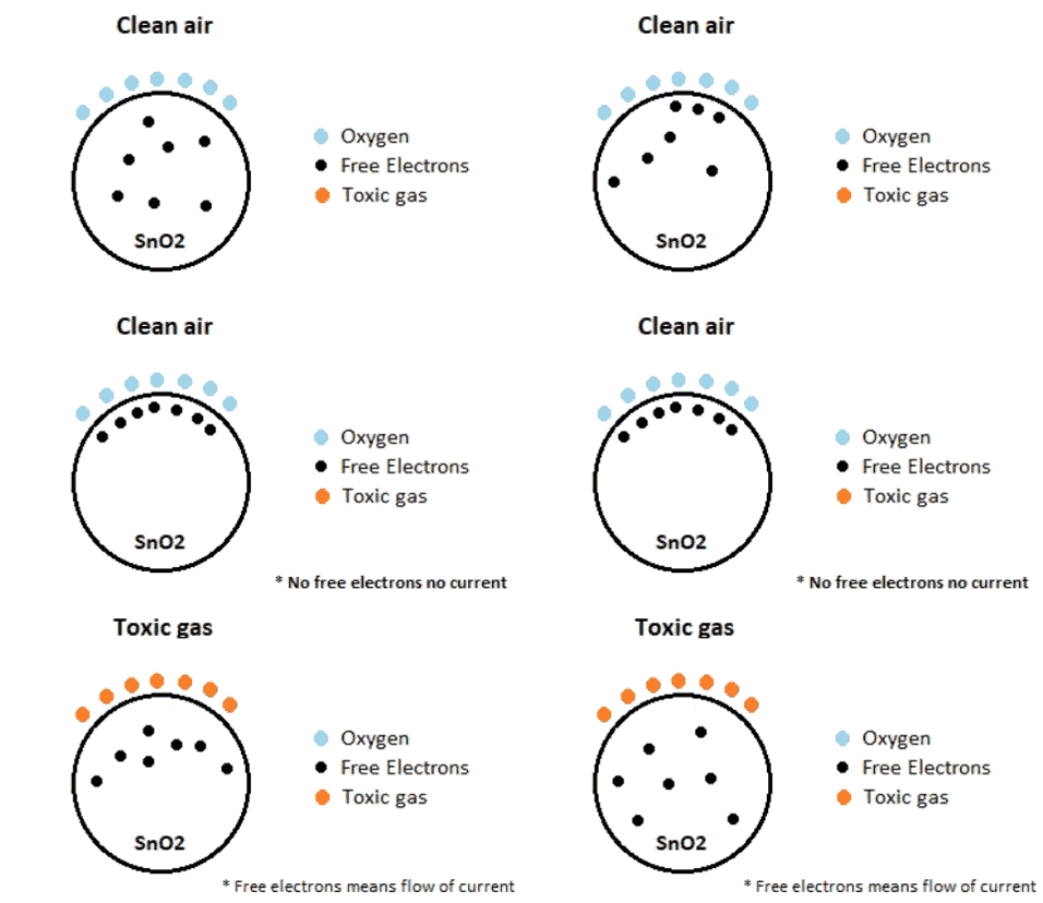
When the sensor is placed in a toxic or combustible gas environment, the reducing gas (orange color) reacts with the adsorbed oxygen particles and breaks the chemical bond between oxygen and free electrons thus releasing the free electrons. As the free electrons are back to their initial position, they can now conduct current, this conduction will be proportional to the number of free electrons available in SnO2, if the gas is highly toxic more free electrons will be available.
How to use a Gas sensor?
A basic gas sensor has 6 terminals of which 4 terminals (A, A, B, B) act as input or output and the remaining 2 terminals (H, H) are for heating the coil. Of these 4 terminals, 2 terminals from each side can be used as either input or output (these terminals are reversible as shown in the circuit diagram) and vice versa.
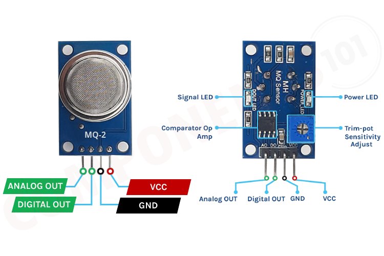
These sensors are normally available as modules (shown right), these modules consist of the gas sensor and a comparator IC. Now let’s see the pin description of the gas sensor module which we will generally use with an Arduino. The gas sensor module basically consists of 4 terminals
- Vcc – Power supply
- GND – Power supply
- Digital output – This pin gives an output either in logical high or logical low (0 or 1) that means it displays the presence of any toxic or combustible gases near the sensor.
- Analog output – This pin gives an output continuous in voltage which varies based on the concentration of gas that is applied to the gas sensor.
As discussed earlier the output of a gas sensor alone will be very small (in mV) so an external circuit has to be used in order to get a digital high-low output from the sensor. For this purpose, a comparator (LM393), an adjustable potentiometer, and some resistors and capacitors are used.
The purpose of LM393 is to get the output from the sensor, compare it with a reference voltage and display whether the output is logically high or not. Whereas the purpose of the potentiometer is to set the required threshold value of the gas above which the digital output pin should go high.
The below diagram shows the basic circuit diagram of a gas sensor in a gas sensor module
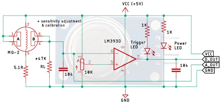
Here A and B are the input and output terminals (Pins 1,3, and 4,6, these are reversible - which means any of the paired terminals can be used as input or output) and 2 and 5 are the Heater coil terminal. If no input voltage is applied to the heater coil, then the output current will be much less (which is negligible or approximately 0). When sufficient voltage is applied to the input terminal and heater coil, the sensing layer wakes up and is ready to sense any combustible gases nearby it. Initially let’s assume that there is no toxic gas near the sensor, so the resistance of the layer doesn’t change and the output current and voltage are also unchanged and are negligible (approximately 0).
Now let’s assume that there is some toxic gas nearby. As the heater coil is pre-heated it is now easy to detect any combustible gases. When the sensing layer interacts with the gases, the resistance of the material varies and the current flowing through the circuit also varies. This change in variation can be then observed at the load resistance (RL). The value of load resistance (RL) can be anywhere from 10KΩ to 47KΩ. The exact value of the load resistance can be selected by calibrating it with the known concentration of the gas. If low load resistance is selected, then the circuit has less sensitivity and if high load resistance is selected then the circuit has high sensitivity.
In the rest of the circuit, we have an LM393 op-amp which is a low-power low-offset voltage op-amp that can be powered from a +5V supply. The main job of this op-amp is to convert the incoming analog signal to a digital signal. Other than that, we also have an onboard 10K potentiometer that is used to adjust the sensitivity of the Gas Sensor module or the triggering voltage of the module. Other than that, we have two LEDs. The first one is a power LED, and the other one is the trigger LED. The power LED turns on when power is applied to the board and the trigger LED turns on when a certain set threshold is reached. Finally, we have two decoupling capacitors that are used to reduce noise in the board.
Most Popular Gas Sensors
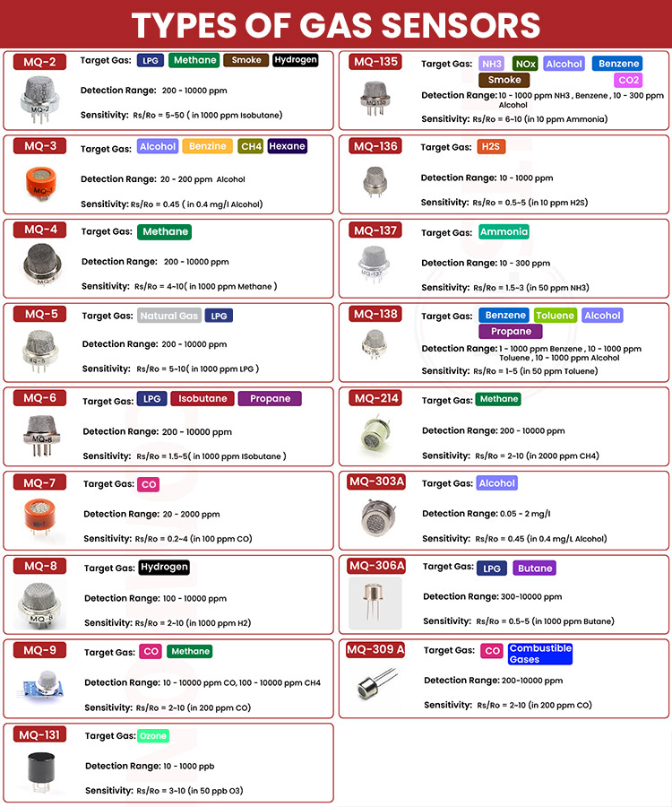
Some of the most popular semiconductor gas sensors includes MQ-2, MQ-3, MQ-4, MQ-5, MQ-6, MQ-7, MQ-8, MQ-9, MQ-131, MQ-135, MQ-136, MQ-137, MQ-138, MQ-214, MQ-303A, MQ-306A and MQ-309A. Here are the most important specifications of these sensors.
Applications of Gas Sensors
- Used in industries to monitor the concentration of toxic gases.
- Used in households to detect emergency incidents.
- Used at oil rig locations to monitor the concentration of the gases that are released.
- Used at hotels to prevent customers from smoking.
- Used in air quality checks at offices.
- Used in air conditioners to monitor the CO2 levels.
- Used in detecting fire.
- Used to check the concentration of gases in mines.
- Breath analyzer.


