CH341 High-Speed USB to Serial Chip
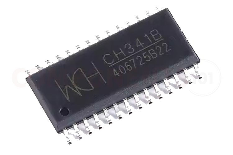
The CH341 is a convenient and cost-effective USB-to-serial UART converter chip designed by WCH (Nanjing QinHeng Corp). The CH343 is widely used in embedded systems and microcontroller communication. It provides USB connectivity between circuits and computers. CH341 is compatible with USB 1.1, and USB 2.0 It supports various protocols such as UART, I2C, SPI, and parallel interfaces. CH341 chip can communicate with printers using the parallel interface in both directions, enabling features like printer status feedback, bidirectional printing, and other functionalities specified in the IEEE-1284 standard. The IC works on 3.3V to 5V. This IC is Available in SOP and SSOP Package. It's versatile and relatively easy to use, making it a popular choice in the maker and embedded systems communities.
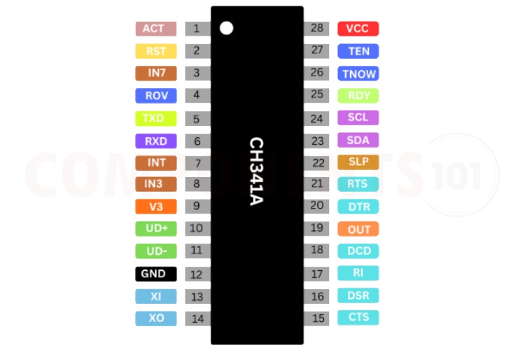
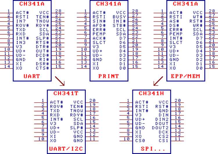
CH341 Pinout Configuration
Here are the pinout details for CH341.
CH341T and CH341H adopt the SSOP-20 package, the simple vision of CH341A, the pins with the same pin name have the same function of them. The multiply VCC pins parallel connect as VCC and multiply GND pins parallel connect as GND in CH341T and CH341H.
| Pin No
341A |
Pin No
341T |
Pin No 341H |
Pin Name |
Pin Type |
Pin Description |
| 28 | 13,20 | 20 | VCC | POWER | A positive power input port requires a 0.1uF power decoupling capacitance |
| 12 | 11,12 | 7,18 | GND | POWER | Public ground, ground connection for USB bus |
| 9 | 6 | 4 | V3 | POWER | Attachment of VCC input external power while 3.3V; connects of 0.01uF decoupling capacitance outside while 5V |
| 13 | 9 | 8 | XI | IN | Input of crystal oscillator, attachment of crystal and crystal oscillator capacitance external |
| 14 | 10 | 9 | XO | OUT | Opposite output of crystal oscillator, attachment of crystal and crystal oscillator capacitance outside |
| 10 | 7 | 5 | UD+ | USB signal | Directly connects to D+ data wire of USB bus |
| 11 | 8 | 6 | UD- | USB signal | Directly connects to D- data wire of USB bus |
| 1 | 1 | 1 | ACT# | OUT | After the USB device configuration output status, low active |
| 2 | No | 2 | RSTI | IN | The input of external reset, active with high-level, with pull-down resistor |
| 24 | 16 | No | SCL | Open Darin Output | The output of chip function configuration, with a pull-up resistor, connect with SCL of serial EEPROM configuration chip |
| 23 | 15 | No | SDA | drain open OUT/IN | Input of chip function configuration, with pull-up resistor, connect with SDA of serial EEPROM configuration chip |
Features of CH341
CH341 USB to Serial converter has the following key features:
- The full-speed USB device interface conforms to USB Specification Version 2.0, and only needs crystal and capacitance external.
- Optional: Define vendor ID, production ID and list number through external low-cost serial EEPROM.
- Supports 5V and 3.3V power sources.
- Low-cost, directly convert serial peripheral equipment, parallel printer and parallel peripheral equipment.
- SOP-28 and SSOP-20 packages are lead-free and compatible with RoHS.
- Only compatible with the application layer because interfaces are diverted via USB.
- Simulate standard serial used to upgrade serial peripheral equipment or increase extra serial via USB.
- Totally compatible with serial application program of computer Windows operation system.
- Hardware full-duplex serial, on-chip transform and receive buffer, supports 50bps~2Mbps communication baud rate.
- Supporting five, six, seven or eight data bits, supporting odd, even, blank, token and no check.
- Supporting serial transfer and receive enable and serial receive ready etc transfer speed control signal and MODEM liaison signal.
- Providing RS232, RS485 and RS422 interface through adding level switch equipment external.
- Supporting indirect access to outside serial EEPROM memory through standard serial communication. 2.3. Printer port
- The Standard USB printer port used to upgrade the parallel printer conforms to relevant USB specifications.
- Compatible with Windows operation system, totally compatible with application programs under Windows 2000 and XP without drive program.
- Supports various standard parallel printers, low-speed and high-speed print modes are optional.
- Supports bi-directional communication of IEEE-1284 specification, supports single directional and bi-directional transfer printer. 2.4. Parallel
- Providing two interface modes: EPP and MEM.
- EPP mode supplies AS#, DS# WR# etc signal, similar to EPP V1.7 or EPP V1.9.
- MEM mode supplies A0, RD# and WR# etc signals, similar to memory read/write mode. 2.5. Synchronous serial
- Adopts FlexWire TM technology, realises various 2-wire to 5-wire synchronous serial via software.
- As the Host/Master endpoint supports 2-wire and 4-wire etc common synchronous serial.
- 2-wire interface supplies SCL and SDA signal wire, supports four kinds of transfer speed.
Manufacturers of CH341:
The CH341 is manufactured by WCH. There are no alternative manufacturers for the same part number as of the date of writing this article.
CH341Variants.
The CH9102 have 3 variants, and they come in 2 different packages SOP28 and SSOP20.
| Package shape | Width of plastic | Width of plastic | Pitch of Pin | Pitch of Pin | Instruction of package | Part Number |
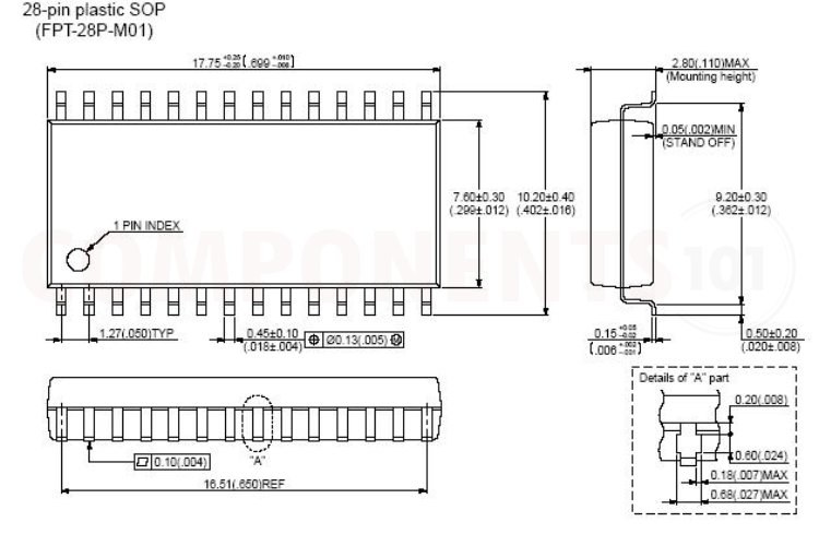
| SOP-28 | 7.62mm | 300mil | 1.27mm | 50mil | Small outline package of 28-pin | CH341A |
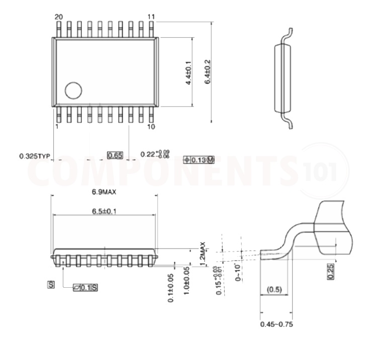
| SSOP-20 | 5.30mm | 209mil | 0.65mm | 25mil | Shrink small outline package of 20-pin | CH341T |
| SSOP-20 | 5.30mm | 209mil | 0.65mm | 25mil | Shrink small outline package of 20-pin | CH341H |
CH341 Equivalents
There are no pin-to-pin compatible Equivalents for CH341.
CH341 Alternatives
If you are looking for an alternative for CH341 you can look at the other ICs from these.
CH340, MA112AS16, FT230x, CP2102, PL2303HX, CH9102, CH343, MCP2200, CP2110, FT232
Note: Complete technical details can be found in the CH341 datasheet at this page’s end.
CH341 Schematics
The following image shows the typical circuit diagram for CH341.
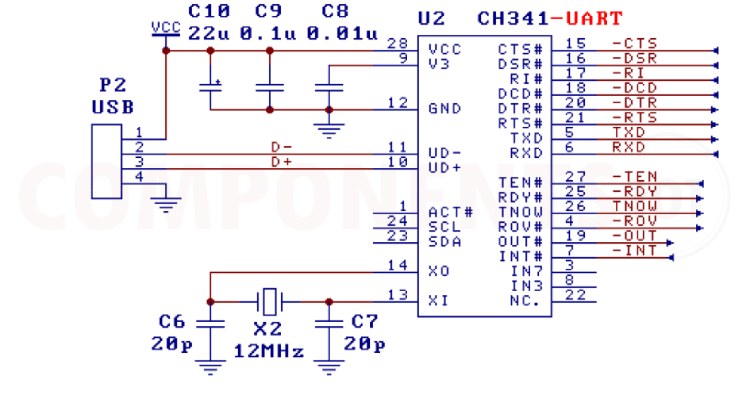
This circuit shows the basic configuration of the CH341 IC, as you can see, the data lines of the USB are directly connected to the UD+ and UD- pins of the IC. The capacitors connected across the power supply and pin V3 is to stabilise the voltage and reduce the noise. We can connect the Tx and Rx lines of CH341 to any microcontroller or similar circuits. Remember to connect the Tx to the Rx of the receiver and the Rx to the Tx of the receiver. Also, make sure that the grounds are commonly connected. Here we used a 12MHz crystal with two 20pf capacitors to provide the clock signal to CH341.
Having troubles with CH341?
I made a USB-to-serial converter using CH341, but I am unable to communicate?
It's due to several reasons but you can check these:
- Double-check all connections between the CH341 chip and the other components of your circuit. Make sure that the TX and RX lines are connected correctly to the devices you are trying to communicate with.
- Check that the voltage levels of the signals (TX, RX, etc.) are compatible with the devices you are connecting to.
- Sometimes, the issue could be with the USB cable itself. Try using a different USB cable to see if that resolves the problem.
Can we program EEPROMs directly with CH341?
Yes, you can program I2C and SPI EEPROMs with CH341. There are even cheap ready-made CH341 programmers available as CH341A programmer or CH341 BIOS programmer.
How to test CH341?
Make sure that the serial settings (baud rate) on your computer match those of the device you are trying to communicate with. Try connecting the TX and RX pins of the CH341 together (a loopback test). Send some data from your computer, and if it's received correctly, it indicates that the CH341 is working.
My computer is not recognizing the IC.
- Make sure that you have the correct drivers installed for the CH341 chip on your computer. The drivers are necessary for the computer to recognize and communicate with the chip.
- In Windows, check the Device Manager to see if the CH341 is recognized correctly without any error messages. If there are errors, it could indicate a driver issue or a problem with the hardware connection.
CH341 PCB Design Choices
What are the design considerations when designing a PCB using CH341?
- Decoupling capacitance must be kept near CH341 Pins.
- Make sure D+ and D- are parallel and supply ground or copper pour besides to decrease the disturbance from the external signal.
- The relevant signal leads between XI and XO must be kept as short as possible. In order to lessen the high-frequency clock disturb outside, setting ground wire on the circle or covering copper to the relative equipment.
- Place the USB port near the CH341 IC, and the data lines track should route straight forward. The D+ and D- signal lines are placed close to the parallel wiring, and ground or copper should be provided on both sides to reduce signal interference from the other parts.
- Minimize the via count in data lines.
Applications of CH341
- Microcontroller Programming
- Debugging and Testing
- Industrial Control Systems
- DIY Electronics Projects
- Legacy Device Support
- Automation and Robotics
- USB to RS485 conversion.
- USB to RS232 conversion.
- USB to TTL serial port conversion.
Footprint and Dimensional information for CH341
Here you can find the mechanical drawings of CH341 along with its dimensions. The dimensions can be used to create custom footprints of the chip and be used for PCB or CAD modelling.