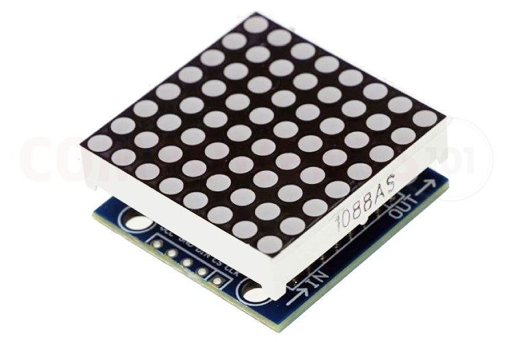
MAX7219 8x8 LED Matrix Module
The MAX7219 8x8 LED matrix module is a compact and versatile display module popular among electronics hobbyists and developers working on microcontroller-based projects. This module utilizes the MAX7219 LED driver IC, which effectively simplifies the process of connecting and controlling multiple LEDs. Capable of controlling up to 64 individual LEDs in an 8x8 grid, the module can display characters, symbols, and animations by individually addressing each LED. The module only needs 3 control signals thus reducing the number of pins needed. Its daisy-chainable feature allows for the expansion of the display without requiring additional microcontroller pins by connecting multiple modules together. The MAX7219 module operates on a simple serial interface, making it compatible with most microcontrollers, including Arduino and Raspberry Pi. This ease of use, combined with its low power consumption and high visual impact, makes it an ideal choice for DIY projects, digital signage, and interactive displays.
MAX7219 LED Matrix Module Pinout
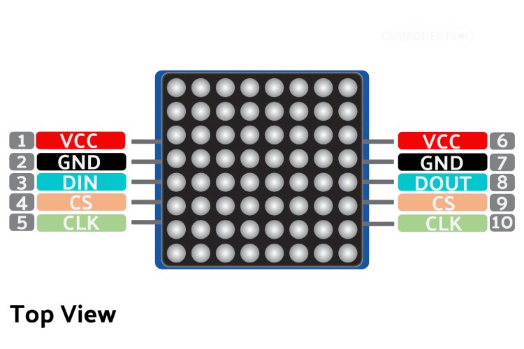
The MAX7219 LED matrix module has ten connections, five of which are for interfacing with the microcontroller and the other five are for daisy-chaining to the next module. Here is the PCB with the LED module removed for easy understanding followed by the pinout.
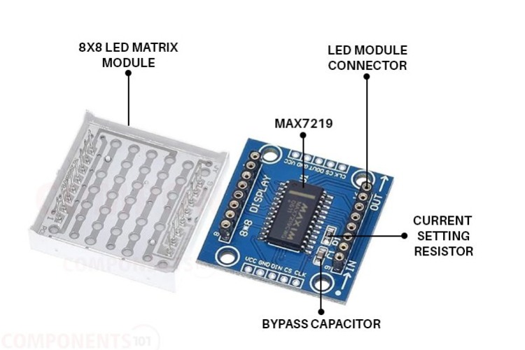
| Pin Number | Pin Name | Function |
| 1,6 | VCC | VCC In/Out |
| 2,7 | GND | GND In/Out |
| 3 | DIN | Data In |
| 4,9 | CS | Chip select In/Out |
| 5,10 | CLK | Clock signal In/Out |
| 8 | DOUT | Data Out to the next module |
MAX7219 8x8 LED Module Specifications
- Wide Operating Voltage: 3.7 to 5.3 V
- Input Current: 320 mA
- 8 x 8 dot matrix Display
- Serial Interface Control: Allows for control using a simple serial communication protocol, minimizing the number of microcontroller pins needed.
- Cascadable Design: Multiple MAX7219 modules can be daisy-chained to create larger displays without using additional microcontroller pins.
- Individual LED Control: Each of the 64 LEDs in the 8x8 matrix can be individually controlled, enabling the display of a wide range of characters, symbols, and animations.
- Brightness Control: Supports adjustable brightness levels, which can be programmed via software to suit different lighting conditions.
- Low Power Consumption: Efficient power management makes it suitable for portable battery-operated devices.
- Compact Form Factor: Its small size makes it ideal for space-constrained applications.
- Digital Error Correction: Automatically detects and corrects any errors in the communication data, ensuring reliable performance.
- Versatility: This can be used with popular microcontrollers like Arduino, Raspberry Pi, and others, which facilitates integration into various projects.
- PCB Dimensions: 30 x 30 x 1 mm
Alternate Display Solution
If you are looking for a display for your project you could also check out the following type of display:
16x2 LCD, 7-segment display, TM1637 4-digit display module, 2.4” TFT, 128x64 LCD, LED Bar Display, OLED Display, Nokia 5110 LCD
MAX7219 LED Matrix Module Circuit Diagram
Here is the circuit diagram for the MAX7219 display module.
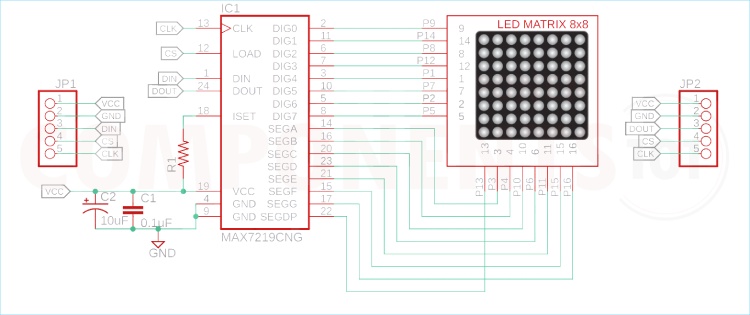
As you can see in the MAX7219 LED Matrix Module schematic, there is not anything complicated about the whole circuit. The control line for the segments and digits are connected as per the MAX7219 datasheet. Other than that, a filter and a decoupling capacitor are connected to the power line as they are recommended for power line filtration. And finally, the current limiting resistor needs to be set by the user to adjust the brightness.
MAX7219 LED Matrix Display Arduino Interfacing
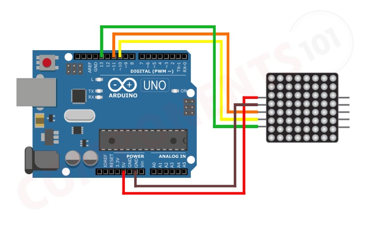
For interfacing with Arduino do the connections as per the circuit diagram above. Connect VCC and GND to 5V and GND pins. Connect DIN to Pin 11, CLK to Pin 13 and CS to Pin 10.
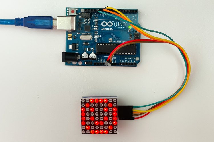
Once the connection is done, in the Arduino IDE Install the MD_MAX72xx Library and copy the given code to a new sketch. Compile the code then upload it to the Arduino. Now you can see a smiley face animation on the display. To learn more about MAX7219 display interfacing please check out the Interfacing MAX7219 LED Dot Matrix Display with Arduino article.
The code for the above animations can be found on MAX7219 Arduino Interfacing.
How to program MAX7219 8x8 Display Driver IC?
You might be wondering, how the MAX7219 is controlling 64 LEDs with just 16 pins. To understand that let's look at the internal connections of an 8x8 LED matrix display.
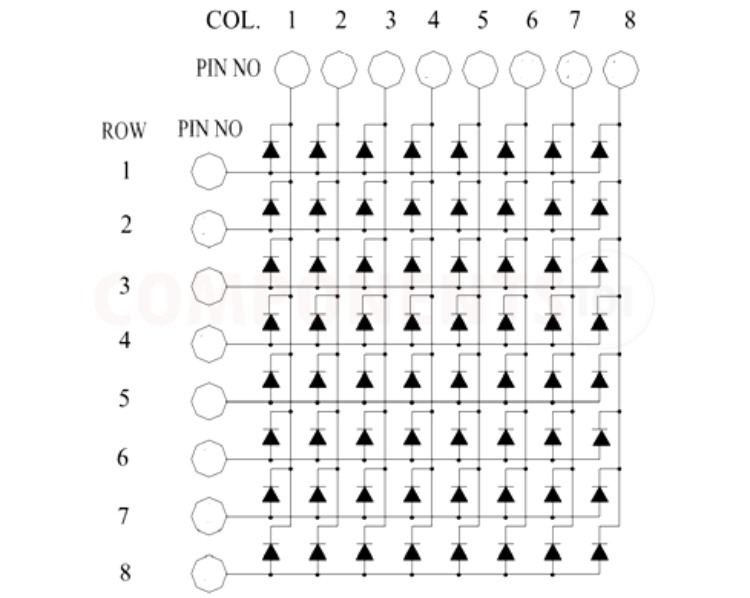
As you can see the display module itself is built using an array of LEDs, consisting of 8 rows and 8 columns. When using this display we are only able to control one row at a time. That is, we will urn on the corresponding row and then manipulate each LEDs in that row. Then we will do the same for the next row and will continue it in a loop. Since this is done at a very fast pace the display will appear to be displayed in whole to our eyes due to the persistence of vision. To understand it easily we have illustrated the same below.
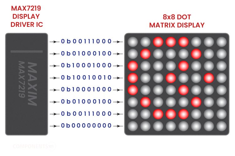
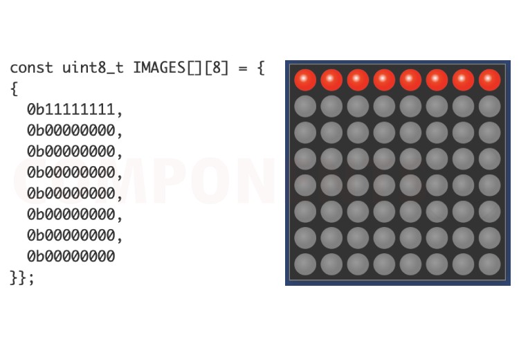
As we discussed we can display any letters or characters that can be created using an 8x8 pixel array. Creating such a character array is pretty simple. All we are doing is that we are storing each character as byte arrays, ie each frame will have 8 bytes, representing 8 rows. In each byte, each bit will represent 8 LEDs in a row. For example, if we need to display a line using the first row of LEDs, the byte array will look something like this.
Connecting Multiple Display Modules
As we mentioned earlier, these displays can be daisy-chained to connect multiple modules together. Daisy-chaining MAX7219 LED matrix modules is a highly effective way to create larger and more complex displays without requiring additional microcontroller pins beyond the initial setup. This method involves connecting multiple LED matrix modules in a series, where the output of one module feeds directly into the input of the next. The main advantage of daisy chaining is only a single connection to the microcontroller is needed for data transmission, as the first module in the chain will pass the data along to subsequent modules. The same clock and load signals from the microcontroller are shared across all chained modules. Click the following image to see how such bigger display modules are created by daisy-chained together, and how to interface them with an Arduino:

MAX7219 LED Matrix Display Module Not working?
Troubleshooting issues with the MAX7219 LED matrix display module can often be key to ensuring its optimal performance. Here’s a straightforward guide to help diagnose and resolve common problems:
Nothing is displayed on the module.
Ensure that the power supply is correctly connected and delivering the appropriate voltage (typically 5V). Double-check all wiring connections to make sure there are no loose or incorrect connections. Review the code to ensure it is correctly initialising and controlling the display.
Dim or Flickering Display
Use software commands to adjust the brightness level to see if the display stabilises. Confirm that the power supply can handle the load, especially if multiple modules are chained.
Inconsistent Display Across Modules
When daisy-chaining modules, ensure that the same initialization and control code is sent uniformly across all modules. Faulty or loose connectors or cables between modules can cause inconsistencies. Check and replace if necessary.
Garbled or Incorrect Output
Ensure that the data-in and data-out connections are secure and correctly configured. Ensure that the SPI communication settings (like clock speed and mode) match the requirements of the MAX7219.
Programming Issues
Make sure you are using the correct libraries or drivers for the MAX7219. Incorrect libraries can cause numerous display issues. Adjust the refresh rate in your code. A very low or high refresh rate can cause flickering or unstable displays.
Cascade Failure
In a daisy-chain setup, a problem in one module can affect all subsequent modules. Inspect each module and connection in the sequence.
By methodically working through these troubleshooting steps, you can identify and solve most issues with the MAX7219 LED matrix display module.
Applications
- LED Signage
- Advertising billboards
- Public Information
- Retail Displays
- Entertainment Venues
- Industrial Monitoring
- Healthcare Notifications
- Educational Tools
- Wearable Technology
- Art Installations
- DIY Projects
MAX7219 LED Matrix Display Dimensions
Here are the dimensions for the MAX7219 LED matrix display module. It will come in handy if you want to create a custom footprint or an enclosure.
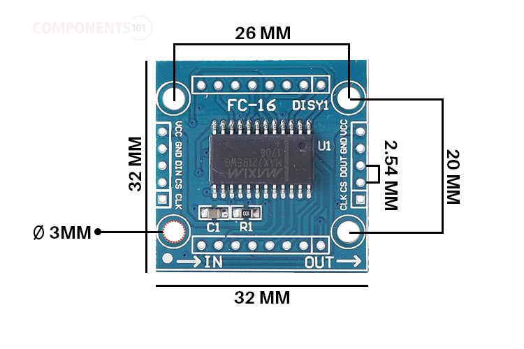
The module comes with the dimensions of 32mmx32mm. The input and output connectors come with a pin pitch of 2.54mm which is standard for most DIY modules. The module also features four mounting holes with provision for M3 screws.

