MAX7219 – 8-Digit LED Display Driver IC
The MAX7219 is an IC designed to control a 8x8 LED MATRIX. The IC is serial input common-cathode (Common Negative) display drivers that interface microprocessors (or microcontroller) to 7-segment numeric LED displays of up to 8 digits, bar-graph displays, or 64 individual LEDs.
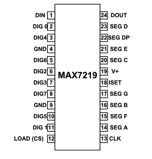
MAX7219 Pin Configuration
MAX7219 is a 24-pin IC available in different packages and is selected depending on the requirements. The description for each pin is given below.
|
Pin Number |
Description |
|
COMMON CATHODE OF DISPLAY SEGMENTS |
|
|
2 |
DIG0- Common ground for all eight segments of DIGIT0 |
|
11 |
DIG1- Common ground for all eight segments of DIGIT1 |
|
6 |
DIG2- Common ground for all eight segments of DIGIT2 |
|
7 |
DIG3- Common ground for all eight segments of DIGIT3 |
|
3 |
DIG4- Common ground for all eight segments of DIGIT4 |
|
10 |
DIG5- Common ground for all eight segments of DIGIT5 |
|
5 |
DIG6- Common ground for all eight segments of DIGIT6 |
|
8 |
DIG7- Common ground for all eight segments of DIGIT7 |
|
SHARED TERMINALS |
|
|
4 |
GND |
|
19 |
V+- Power Supply |
|
SHARED SEGMENT TERMINAL OF ALL EIGHT DIGITS |
|
|
14 |
SEG A – SEGEMTENT A of all DIGITS |
|
16 |
SEG B – SEGEMTENT B of all DIGITS |
|
20 |
SEG C – SEGEMTENT C of all DIGITS |
|
23 |
SEG D – SEGEMTENT D of all DIGITS |
|
21 |
SEG E – SEGEMTENT E of all DIGITS |
|
15 |
SEG F – SEGEMTENT F of all DIGITS |
|
17 |
SEG G – SEGEMTENT G of all DIGITS |
|
22 |
SEG DP – SEGEMTENT DOT of all DIGITS |
|
FUNCTION PINS |
|
|
1 |
DIN - Serial Data Input Pin |
|
12 |
LOAD(CS) – Chip Select or Data shift pin |
|
13 |
CLK - Clock Pin |
|
24 |
DOUT - Pin used to Connect Second chip serially |
|
18 |
ISET - current output adjust pin |
Features and Specifications
- Operating voltage range: +4.0 to +5.5V
- Recommended operating voltage: +5V
- Maximum supply voltage: 6V
- Maximum current allowed to draw through each segment pin: 100mA
- Maximum current allowed to through each DIGIT ground pin: 500mA
- Low power consumption
- Data-to-Segment Delay Time: 2.2mSec
- Operating temperature: 0°C to +70°C
- Storage Temperature: -65°C to +150°C
Note: Complete technical information can be found in the MAX7219 Datasheet linked at the bottom of this page.
Similar ICs
Where to use MAX7219 IC
1. This IC is basically used where you want to convert serial data to parallel data.
2. The chip is used to reduce I/O pin usage of controller or processor.
3. Used to control 64 LEDs using only 3 PINS
4. Preferred when controller 7 Segment Displays. The chip can control up to 8 DIGIT.
5. Can be used to control more display segments by connecting more chips in serial.
How to use MAX7219 IC
The chip is used similar to any shift register. First we will send serial data to chip bit by bit .once all data is sent we will tell chip to shift this serial data to output by enabling CS pin. The step by step procedure of working goes as below.
- First connect DIN, CS and CLK pin. These three pins are important to controlling chip.
- Next is selecting resistor for ISET pin. As we know that there is no standard parameter for segment displays in market. They have different voltage and current setting. In order to drive the display without error we will choose the appropriate resistor by using the following table.
|
Forward voltage |
|||||
|
ISeg |
1.5V |
2.0V |
2.5V |
3.0V |
3.5V |
|
40mA |
12.2kΩ |
11.8kΩ |
11.0kΩ |
10.6kΩ |
9.69kΩ |
|
30mA |
17.8kΩ |
17.1kΩ |
15.8kΩ |
15.0kΩ |
14.0kΩ |
|
20mA |
29.8kΩ |
28.0kΩ |
25.9kΩ |
24.5kΩ |
22.6kΩ |
|
10mA |
66.7kΩ |
63.7kΩ |
59.3kΩ |
55.4kΩ |
51.2kΩ |
- There are two ways to use this chip. One is to follow the instructions given in datasheet to send the data bit by bit. Second way is to use libraries previously written for this chip. Using the libraries is easiest way to get the required result.With libraries you can just enter the required data to send without worrying anything.
- We will send data to the chip through DIN pin. The data is sent BIT by BIT by setting the clock of chip for each bit. The Chip stores the serial data its registers until all data is received. After completing data sending we will set the CS pin for the chip to shift all data stored in its register to the output.
- Once the data is put out by the chip it will light up the corresponding LEDs to display the result.
Applications
- General purpose SHIFT operation
- Measuring Instruments
- Digital Electronics
- Servers
- Memory units
- Networking
- Digital systems
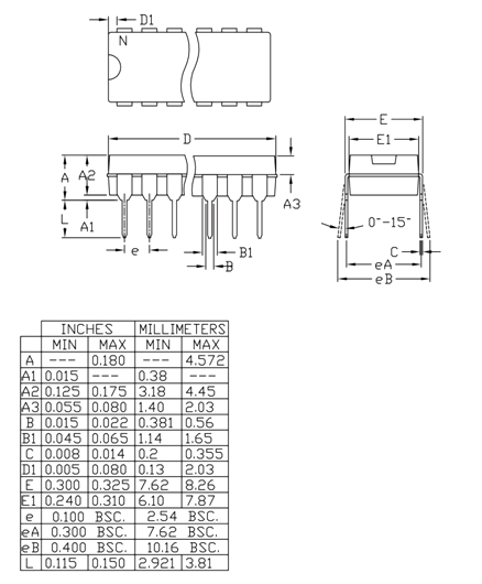
2D Model and Dimensions
Measurements in (Inches/millimeters)