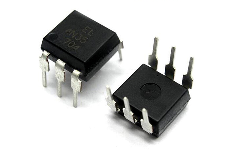
EL4N35 Optocoupler IC
Features and Specifications
This section mentions some of the important features and specifications of the optocoupler IC.
- Number of Channels: 1 Channel
- Maximum Collector-Emitter Voltage: 30V
- Forward Current: 100mA
- Forward Voltage: 1.5V
- Reverse Voltage: 6V
- Isolation Voltage: 5300 Vrms
- Operating Temperature: -55 to 100 Degree C
- Power dissipation: 250 mW
Note: More technical information can be found in the 4N35 Datasheet, linked at the bottom of this page.
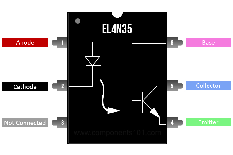
4N35 Pinout Configuration
The IC comes as a dual inline package and has 6 pins. The table below can be referred to understand the pin configuration of the IC.
|
Pin Number |
Pin Type |
Pin Description |
|
1 |
A |
Anode |
|
2 |
C |
Cathode |
|
3 |
NC |
Not Connected |
|
4 |
E |
Emitter |
|
5 |
C |
Collector |
|
6 |
B |
Base |
Working of the Optocoupler IC
The optocoupler IC consists of gallium arsenide infrared LED and a silicon NPN phototransistor and using the IC is also pretty easy. To use the IC as a phototransistor we will not be needing the base pin(pin 6). The working circuit below can be followed to design your own circuit and get the optocoupler IC to use.
The infrared LEDs anode(pin1) and cathode(pin 2) pins are to be connected to the logic input and the ground, respectively. The collector pin(pin 5) is pulled up using a resistor and the output device is connected to the other end. Here for our case, we have connected an output probe to monitor the output. The emitter pin(pin 4) is to be grounded.
Note: Do not connect the emitter and the cathode pin to the same ground as they are meant to be isolated.
Working: When the IR LED is provided with a logic 0 input the LED will be in OFF condition and will not trigger the transistor and the output we will receive is a HIGH across the collector-emitter terminal. Whereas, when the LED is provided with a logic 1, LED will turn on and trigger the transistor and shorts the collector-emitter junction and we will receive a 0 at the output.
Note: The Collector-emitter voltage can be set up to a maximum of 30V.
Alternatives
Available Packages
DIP 6
Applications
Here are some of the applications of the EL4N35 optocoupler IC.
- Relay driving circuits
- Switch-mode power supply feedback
- AC mains detection
- Logic ground isolation
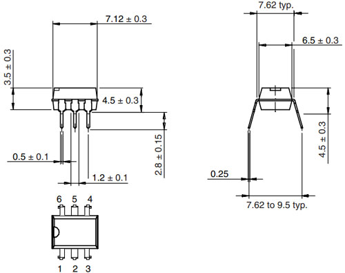
2D Model and Dimensions
Below is the 2D model of the optocoupler IC along with its dimensions in millimeters. The following information can be used in order to create custom footprints of the IC and be used for PCB designing and CAD modelling.