IRF510 N-channel Power MOSFET

IRF510 is a third-generation Power MOSFET with the best combination of fast switching and low on-state resistance. This component is available at a lower cost. Hence, it is widely used in industrial applications for power dissipation levels up to 43W.
IRF510 MOSFET is capable to withstand drain-to-source voltage VDS up to 100V and continuous drain current ID up to 5.6A. It can withstand 20A current in pulse mode and belongs to the package TO-220AB. It is designed for applications that require high-speed switching like a motor driver, switching converter and regulators, etc.
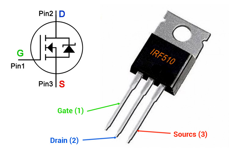
IRF510 Pinout Description
|
Pin No |
Pin Name |
Pin Description |
|
1 |
Gate |
Control the biasing of MOSFET |
|
2 |
Drain |
Current flows-in through Drain |
|
3 |
Source |
Current flows-out through Source |
Features
- Dynamic dv/dt rating
- Single-pulse avalanche rated
- High input impedance
- Linear transfer characteristic
- High-speed switching speed (in terms of nano-second)
- Ease of paralleling
- Operating temperature up to 175˚C
- Low thermal resistance
Applications
The applications of IRF510 are listed below.
- UPS (Uninterruptable Power Supply)
- Battery charger and management system
- Motor driver circuit
- Telecommunication and computer applications
- Solar UPS
- Fast switching applications
- Switching converter and regulators
Technical Specifications
- Transistor Polarity: N-channel
- Drain-to-source voltage VDS: 100V
- Drain-to-source current ID: 5.6A
- On-state resistance (drain-to-source resistance) RDS: 0.54Ω
- Operating temperature range: -55˚C to 175˚C
- Gate charge Qg: 8.3nC
- Gate-source voltage VGS: ±20V
- Maximum power dissipation: 43W
- Maximum voltage required to conduct: 2V to 4V
- Package type: TO-220AB
Note: More technical specifications can be found in the IRF510 datasheet attached at the end of this page.
IRF510 Equivalent
IRF512, IRF120, IRF522, IRF520, IRF634, IRF532
Switching Characteristics
- Turn-on delay time td(on): 6.9ns
- Turn-off delay time td(off): 15ns
- Rise time tr: 16ns
- Fall time tf: 9.4ns
Simulation
This MOSFET is a switching device that will turn on when sufficient gate voltage is available or else, it will remain in turn-off condition. In this simulation, we will use IRF510 to turn on an LED. If the applied gate voltage is not sufficient to turn on the device, the current will not pass from drain to source and the LED will remain in off condition.
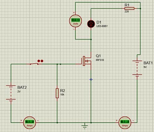
When the gate voltage is sufficient to turn on MOSFET, the LED will turn on and the current will pass through the drain to the source.

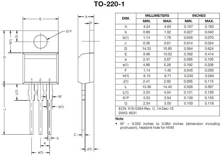
2D Model and Dimensions
If you are designing a PCB or Perf board with this component, then the following picture from the Datasheet will be useful to know its package type and dimensions.