2N7000 – N-Channel MOSFET
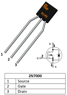
2N7000 MOSFET Pinout Configuration:
|
Pin Number |
Pin Name |
Description |
|
1 |
Source |
Current flows out through Source |
|
2 |
Gate |
Controls the biasing of the MOSFET |
|
3 |
Drain |
Current flows in through Drain |
Features:
- Small signal N-Channel MOSFET
- Drain-Source Voltage (VDS) is 60V
- Continuous Drain Current (ID) is 200mA
- Pulsed Drain Current (ID-peak) is 500mA
- Gate threshold voltage (VGS-th) is 3V
- Gate-Source Voltage is (VGS) is ±20V
- Turn ON and Turn off time is 10ns each.
- Available in To-92 Package
Note: Complete Technical Details can be found in the 2N7000 datasheet given at the end of this page.
2N7000 Equivalent N-Channel MOSFET:
BS170, NTE 491, IRF3205, IRF540N, IRF9Z34N, IRFP250N, IRFZ44.
Where to use 2N7000:
2N7000 is a small signal N-channel MOSFET. MOSFET’s are power electronic switches just like transistors, but with a higher current and voltage rating. The 2N7000 MOSFET can be used to switch loads which operates on less than 60V (VDS) and 200mA (ID). This mosfet comes in a compact TO-92 package and has a threshold voltage of 3V, hence if you looking for a small mosfet to switch a load then this IC could suit your purpose.
How to use 2N7000:
A Mosfet has three terminals - Drain, source and Gate. Current always flows in through the Drain and flows out through the Source. The Gate pin acts as a switch for turning ON or OFF the mosfet. If the gate is connected to Ground then the mosfet is off that is there will be no connection between Drain and source (Open). If the Gate is provided with its gate source Voltage (VGS) then the MOSFET will be ON, that is the Drain and source pin will be connected together (Closed). Thus by controlling the Voltage (VGS) we can switch the Mosfet hence the MOSFET is a voltage controlled device.
The Gate Source Voltage (VGS) is a critical parameter while using the transistor. For this transistor, the VGS is 20V, hence when we provide this voltage the MOSFET will be fully closed. Any values in between 20V is make the MOSFET to close partially thus creating a partial connection. The load which is being switched by the MOSFET can be upto 60V (VDS) and can consume upto 200mA (ID).
I have given a very simple circuit below which uses this MOSFET to control a load motor of 24V 2A. The current and voltage values when the switch is closed and opened can also be observed.
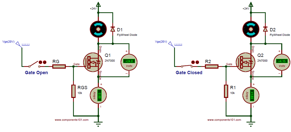
As we know the Gate Source voltage of this Mosfet is 20V, hence we have used 20V to turn ON the MOSFET. When the gate switch is open, the Gate pin of the Mosfet should be connected to ground to turn off the Load, hence we have used a 10K pull down resistor (RGS) to turn off the MOSFET after it is turned ON. The resistor RG is a current limiting resistor which limits the required Gate current. If the load controlled by the Mosfet is a Inductive load like the Motor that we have used here, then it is mandatory to use a Flywheel (a.k.a freewheel) diode safely discharge the charge accumulated by the Inductive coil.
Applications:
- Switching High voltage loads
- Commonly used for small signal switching
- LED dimmers or flashers
- Low power Analog converters or inverters
2D Model and Dimensions
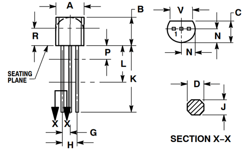
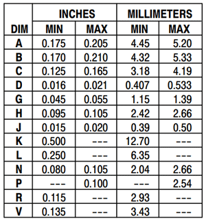
If you are designing a PCB or Perf board with this component, then the following picture from the 2N7000 Datasheet will be useful to know its package type and dimensions.
