W5500 Ethernet Module: Pinout, Specifications, Architecture, and Interfacing
The W5500 Ethernet Module is a high-speed SPI to Ethernet Module interface board powered by WIZnet's W5500 Hardwired TCP/IP embedded Ethernet controller IC. Featuring an integrated 10BaseT / 100BaseTX Ethernet MAC and PHY, an embedded hardware TCP/IP protocol stack, 32 KB of internal buffer memory, and high-speed SPI communication up to 80 MHz, this module enables microcontrollers to establish fast, reliable, and secure wired Internet connectivity with minimal processor overhead.
Unlike software-based Ethernet solutions that consume substantial host microcontroller Flash and SRAM, the W5500 completely offloads network protocol processing (TCP, UDP, IPv4, ICMP, ARP, IGMP, and PPPoE) into dedicated hardware logic. This makes the W5500 Ethernet module particularly well-suited for space-constrained, resource-limited 8-bit, 16-bit, and 32-bit microcontrollers such as Arduino UNO, STM32, ESP32, and Raspberry Pi Pico (RP2040).
This guide covers the W5500 technical specifications, pinout configurations for both the Standard and Mini / Lite Ethernet Module, IC architecture, part marking, SPI host interfacing, and a comparison with classic Ethernet controllers like the W5100 and ENC28J60.
W5500 Technical Specifications
The table below summarises the core W5500 datasheet parameters at a glance, useful as a quick reference before you start wiring the module to a host MCU.
| Parameter | Specification |
| Ethernet Controller IC | WIZnet W5500 (Hardwired TCP/IP Embedded Ethernet Controller) |
| IC Package | 48-Pin LQFP (7 mm × 7 mm, 0.5 mm pitch, Lead-Free) |
| Supported Network Protocols | TCP, UDP, IPv4, ICMP, ARP, IGMPv1/v2, PPPoE |
| Simultaneous Sockets | 8 independent hardware sockets operating simultaneously |
| Internal Buffer Memory | 32 KB embedded SRAM for TX/RX buffers (flexible 1KB–16KB allocation per socket) |
| Ethernet Physical Layer (PHY) | Embedded 10BaseT / 100BaseTX Ethernet PHY |
| Ethernet MAC Layer | Embedded IEEE 802.3 Ethernet MAC |
| Network Features | Auto-Negotiation (Full / Half Duplex, 10 / 100 Mbps), Auto-MDI/MDIX |
| Host Interface | High-Speed Serial Peripheral Interface (Fast SPI, Mode 0 & Mode 3) |
| Max. SPI Clock Frequency | Up to 80 MHz |
| Operating Voltage (Logic) | 3.3 V DC (Core & I/O) |
| I/O Signal Tolerance | 5.0 V I/O tolerant (connects directly to 5V MCUs without level shifters) |
| Module Input Voltage | 5.0 V DC via 5V pin (regulated via onboard AMS1117-3.3) or 3.3 V DC via 3V3 pin |
| Power Consumption | Active Link (100 Mbps): ~132 mA; Power Down Mode: ~13 mA |
| Power Management | Supports Power Down Mode and Wake-on-LAN (WOL) over UDP |
| Network Connector | RJ45 MagJack (HanRun HR911105A / HR961160C) with integrated isolation transformer and status LEDs |
| Onboard Crystal | 25.000 MHz Crystal Oscillator (multiplied internally via PLL to 150 MHz) |
| Dimensions (Standard Module) | ~55.0 mm × 28.0 mm × 15.0 mm |
| Dimensions (Mini / Lite Module) | ~28.5 mm × 23.0 mm × 24.0 mm |
| Pin Pitch | 2.54 mm (0.1") standard pitch |
| Operating Temperature | -40°C to +85°C (Industrial Grade) |
Pinout & Pin Configuration
The W5500 Ethernet controller is commonly available in two popular breakout board form factors: the Standard Blue Module (with a 2×5 10-pin dual-row header and onboard 3.3V LDO regulator) and the Mini / Lite Green Module (with dual 1×6 6-pin single-row headers for ultra-compact embedded designs).
1. Standard W5500 SPI Ethernet Module Pinout
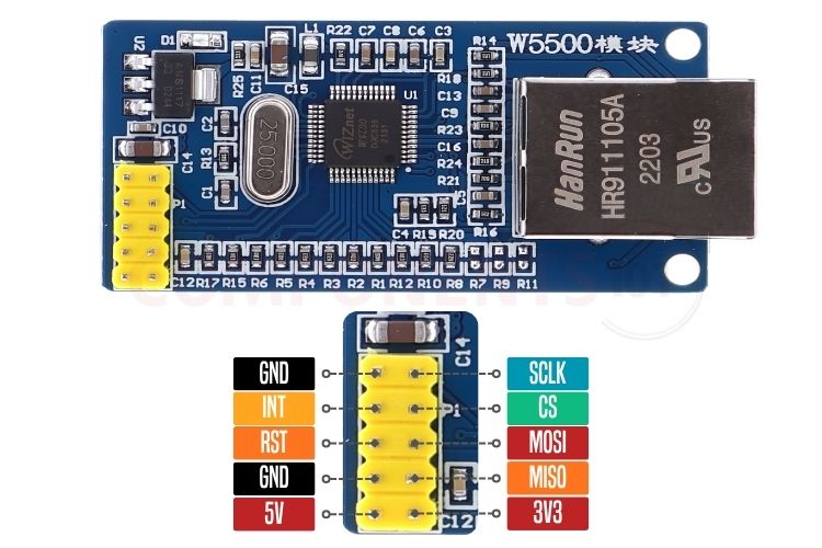
The Standard Blue Module features a 10-pin (2×5) double-row header providing SPI data lines, power rails, hardware reset, and interrupt outputs.
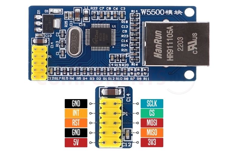
- SCLK, MOSI, and MISO form the standard SPI communication bus. The W5500 supports high-speed SPI transfers up to 80 MHz in both SPI Mode 0 (CPOL=0, CPHA=0) and SPI Mode 3 (CPOL=1, CPHA=1), providing flexible interfacing with virtually any modern microcontroller.
- CS (SCSn - Slave Chip Select) is an active-LOW SPI select signal. Pulling CS LOW initiates an SPI frame, while driving it HIGH terminates the transaction. When multiple SPI devices share the same bus, each device must have a dedicated CS pin driven by the host microcontroller.
- RST (RSTn - Reset) is an active-LOW hardware reset pin. Driving this pin LOW for at least 500 µs completely resets the internal registers, PHY, and MAC of the W5500. It is internally pulled up, but connecting it to a host GPIO allows programmatic hardware resets during initialization or fault recovery.
- INT (INTn - Interrupt) is an active-LOW interrupt output. It alerts the host MCU when specific network events occur on any of the 8 sockets, such as incoming data reception (RECV), connection established (CON), disconnection (DISCON), transmission completion (SENDOK), or timeout (TIMEOUT), eliminating the need for continuous SPI polling.
Standard Module Pin Configuration Table
| Pin Label | Pin Type | Function | Description |
| 5V | Power | Power Input (5V) | 5.0 V DC power input to the onboard AMS1117 3.3V regulator. |
| GND | Power | Ground | Common ground reference. |
| RST | Input | Hardware Reset (RSTn) | Active-LOW hardware reset input. Resets internal registers and PHY. |
| INT | Output | Interrupt Output (INTn) | Active-LOW interrupt output to host MCU (indicates socket events/data). |
| GND | Power | Ground | Additional common ground pin. |
| 3V3 | Power | 3.3V Power Rail (3.3V) | Direct 3.3V DC power input or regulated 3.3V output from onboard LDO. |
| MISO | Output | SPI Master In Slave Out | SPI data output from W5500 to host microcontroller. |
| MOSI | Input | SPI Master Out Slave In | SPI data input from host microcontroller to W5500 (5V tolerant). |
| CS | Input | Slave Chip Select (SCSn) | Active-LOW SPI slave select pin (5V tolerant). |
| SCLK | Input | SPI Serial Clock (SCLK) | SPI clock input driven by host MCU (supports up to 80 MHz, 5V tolerant). |
2. W5500 Mini / Lite Module Pinout
The W5500 Mini / Lite Module is designed for ultra-compact gateway systems where PCB space is at a premium. It breaks out the signals into two single-row 6-pin headers.
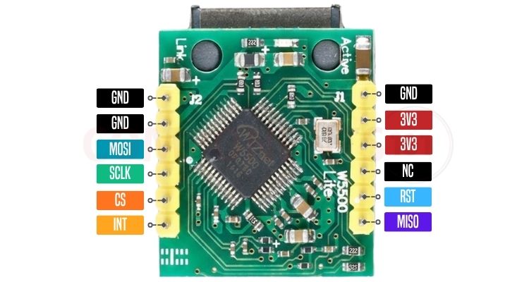
*NOTE: The Mini / Lite module does not include an onboard 5V regulator. It must be powered strictly with a clean 3.3V DC power source via the 3V3 pins. Applying 5V directly to the 3V3 header will permanently damage the W5500 controller IC.
Mini / Lite Module Pin Configuration Table
| Pin Label | Pin Type | Description |
| GND | Power | Common ground reference. |
| GND | Power | Common ground reference. |
| MOSI | Input | SPI Master Out Slave In (5V tolerant). |
| SCLK | Input | SPI Serial Clock line (up to 80 MHz, 5V tolerant). |
| CS | Input | SPI Slave Chip Select (SCSn, active-LOW, 5V tolerant). |
| INT | Output | Active-LOW Interrupt output (INTn). |
| GND | Power | Common ground reference. |
| 3V3 | Power | 3.3 V DC Power Supply input. |
| 3V3 | Power | 3.3 V DC Power Supply input (internally connected to J1 Pin 2). |
| NC | -- | Not connected (Leave floating). |
| RST | Input | Active-LOW Hardware Reset (RSTn). |
| MISO | Output | SPI Master In Slave Out data line. |
3. WIZnet W5500 IC Pin Assignment (48-LQFP)
For engineers designing custom carrier boards and industrial Ethernet hardware, the standalone W5500 IC is packaged in a compact 48-pin LQFP package.
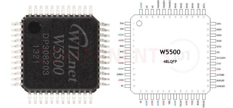
The 48-pin assignment groups the IC into dedicated functional sections:
| Section | Pins | Description |
| Analog Front End | 1-11 | Differential transmit (TXP, TXN) and receive (RXP, RXN) pairs connected directly to the isolation magnetics; external reference resistor EXRES1 = 12.4 kΩ, 1%; analog power AVDD, AGND. |
| Power & Internal Regulator | 13-24 | Core logic supply VDD = 3.3 V; 1.2 V internal core regulator bypass pins 1V2O, TOCAP, VBG; PHY operating mode pins PMODE0-2. |
| Status LED Outputs | 25-27 | Dedicated open-drain, active-LOW outputs: LINKLED (Link Status), DUPLED (Full/Half Duplex), and ACTLED (Network Activity). |
| Oscillator & SPI Interface | 30-36 | Crystal input/output XI/CLKIN, XO @ 25 MHz; SPI/control signals SCSn (Chip Select), SCLK (Clock), MISO (Data Out), MOSI (Data In), and INTn (Interrupt). |
| System Control | 37 | Active-LOW reset input RSTn. |
Hardware Layout & Parts Marking
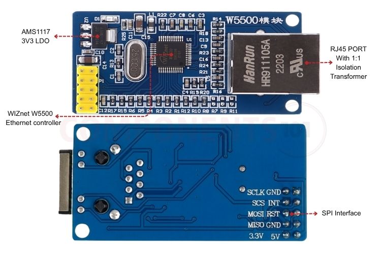
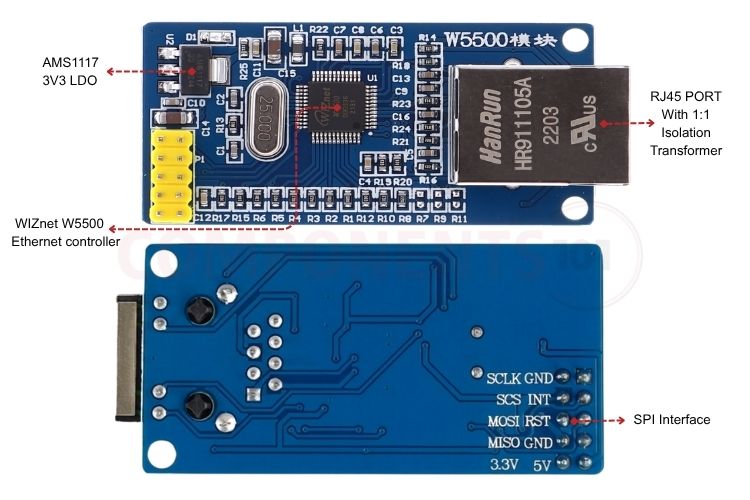
HanRun HR911105A / HR961160C RJ45 MagJack: The RJ45 MagJack provides the physical Ethernet interface and integrates a 1:1 isolation transformer, common-mode chokes, termination components, and front-panel status LEDs. The integrated magnetics provide approximately 1500 V galvanic isolation between the Ethernet cable and the low-voltage electronics, helping protect the circuit from ground-loop currents and electrical surges.
AMS1117-3.3V LDO Voltage Regulator: The AMS1117-3.3V low-dropout regulator converts the incoming 5 V DC supply into a regulated 3.3 V power rail. This regulated supply is used to power the W5500 Ethernet controller and associated Ethernet interface circuitry. The regulator and its required input/output bypass capacitors should be placed appropriately to maintain a stable supply and minimize power-supply noise.
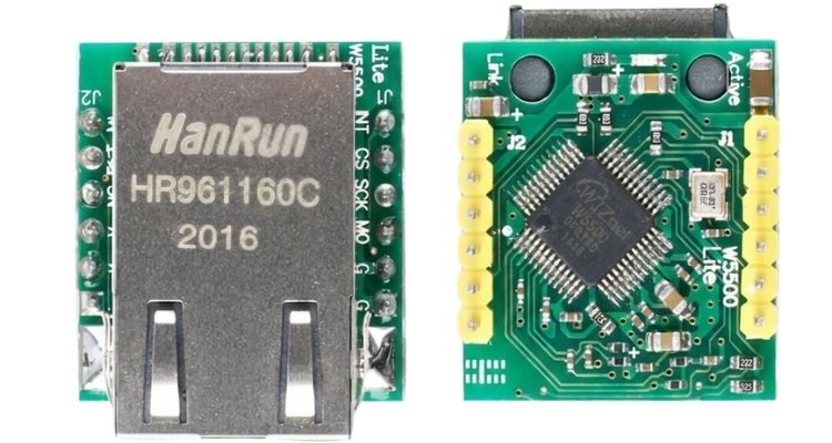
25.000 MHz Crystal Oscillator: A 25.000 MHz crystal provides the reference clock for the W5500. The crystal is connected to the controller's oscillator pins and serves as the baseline frequency for the internal PLL, which generates the 150 MHz operating clock required for high-speed Ethernet packet processing.
Internal Architecture & Hardwired TCP/IP Core
The key differentiator of WIZnet's Ethernet controllers is their proprietary Hardwired TCP/IP Stack (TCP/IP Core). In conventional embedded Ethernet designs (such as the Microchip ENC28J60), the Ethernet controller only handles physical frame transmission (MAC/PHY), leaving the host microcontroller to execute thousands of lines of software stack code (e.g., lwIP or uIP).
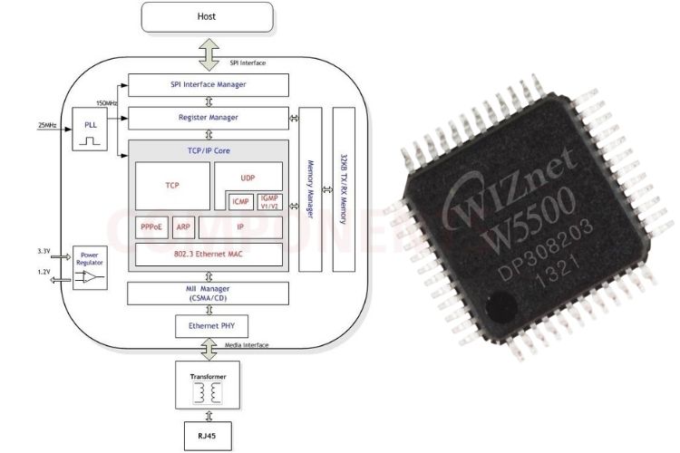
- Fully Hardwired Protocols: The W5500 implements TCP, UDP, IPv4, ICMP, ARP, IGMPv1/v2, and PPPoE using dedicated hardware logic instead of software firmware. This reduces host processor load and provides deterministic network operation.
- Immunity to Network Attacks: The network stack runs in dedicated hardware state machines rather than software memory, reducing exposure to OS-level vulnerabilities and certain buffer-overflow or memory-exhaustion issues. However, it is not completely immune to all network-based DoS attacks.
- Independent Socket Channels: Up to eight independent hardware sockets can operate simultaneously in TCP Server, TCP Client, UDP, or MACRAW modes, supporting multiple network services concurrently.
- Dynamic 32 KB Buffer Allocation: The W5500 provides 32 KB of internal SRAM for TX/RX buffering, which can be allocated among sockets based on application requirements. For example, more memory can be assigned to high-volume HTTP transfers and less to lightweight MQTT or sensor telemetry.
- MII Management & Embedded PHY: The W5500 integrates the MAC and 10/100Base-TX PHY, supporting auto-negotiation and polarity correction while reducing external components and simplifying the Ethernet hardware design.
Microcontroller Interfacing & SPI Operation
The W5500 communicates with the host microcontroller using a standard 4-wire Serial Peripheral Interface (SPI), which is what makes it a true SPI to Ethernet module rather than a parallel-bus device.
High-Speed SPI Frame Protocol
The W5500 SPI protocol uses a 3-phase frame structure consisting of:
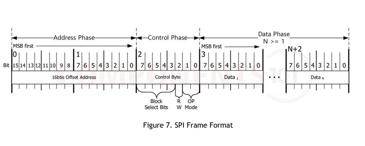
- Address Phase (16-bit): Specifies the 16-bit offset address within the target register block.
- Control Phase (8-bit): Selects the target block (Common Register, Socket 0–7 Registers, or Socket 0-7 TX/RX Buffer) and defines the access mode (Read/Write and Variable/Fixed Data Length).
- Data Phase (N-bytes): Reads or writes the payload data continuously as long as SCSn remains LOW.
Comparison: W5500 vs. ENC28J60 vs. W5100
When selecting an Ethernet controller for embedded development, the W5500 represents the modern gold standard for microcontrollers lacking native Ethernet MACs.
| Feature | WIZnet W5500 | WIZnet W5100 / W5100S | Microchip ENC28J60 |
| TCP/IP Processing | Hardwired TCP/IP Core | Hardwired TCP/IP Core | Software Stack on Host MCU |
| Supported Protocols | TCP, UDP, IPv4, ICMP, ARP, IGMP, PPPoE | TCP, UDP, IPv4, ICMP, ARP, PPPoE | None in silicon (Host must run lwIP/uIP) |
| Hardware Sockets | 8 Sockets | 4 Sockets | Dependent on Host MCU RAM (Typically 1–2) |
| Internal Buffer SRAM | 32 KB (Flexible per socket) | 16 KB (Fixed 4×4KB or 2KB partitions) | 8 KB (Shared TX/RX buffer) |
| Ethernet Speed | 10 / 100 Mbps (100BaseTX) | 10 / 100 Mbps (100BaseTX) | 10 Mbps only (10BaseT) |
| Host Interface | High-Speed SPI (Up to 80 MHz) | SPI (Up to 25 MHz) + Parallel Bus | SPI (Up to 20 MHz) |
| Host MCU RAM Overhead | Negligible (~few bytes) | Negligible (~few bytes) | High (~2 KB to 10+ KB RAM) |
| Host MCU Flash Overhead | Minimal (~3–5 KB driver) | Minimal (~3–5 KB driver) | Heavy (~15–30+ KB software stack) |
| 5V I/O Tolerance | Yes (5V tolerant) | Yes (5V tolerant) | Yes (5V tolerant) |
| Power Management | Power Down & Wake-on-LAN (WOL) | Limited | Power Down mode |
| Thermal Dissipation | Low (Runs cool) | Moderate to High (Runs warm) | Low |
| Best Suited For | High-reliability IoT, Industrial gateways, Web servers | Legacy Arduino Ethernet Shields | Ultra-low-cost basic 10Mbps sensing |
Typical Applications
- Industrial Automation & PLC Gateways: Modbus TCP, MQTT edge gateways, and industrial sensor data loggers.
- Home Automation & Smart Building: Hardwired Ethernet wall controllers, access control badges, and security camera triggers.
- Networked Embedded Devices: Microcontroller-driven web servers, NTP network clocks, remote power switches, and networked relays.
- High-Reliability IoT Nodes: Remote telemetry units operating in electrically noisy environments where wireless Wi-Fi is unreliable or prohibited.