5V 700mA (3.5V) Isolated Switch Power Supply Module
The 5V 700mA isolated switch power supply module is an AC-DC Step-Down converter. It is a very handy module for the electronics makers because it is required to connect the input pins of this module to an AC source directly and it converts that AC input into a 5 Volt DC Power supply with 700mA of current.
Key Features
- Input Current: 0.014A(AC220V)
- Input Voltage: AC 50V 50Hz ~ AC 277V 50Hz
- Output Voltage: DC 5V
- Output Current: 700mA
- Power Dissipation at Maximum Load: 3.5W
- Operating Temperature: -20°C to 60°C
- Output Efficiency: 80%
- This module includes Over Power Protection at Output, Short-Circuit Protection, A temperature protection, An overcurrent Protection.
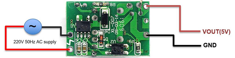
Pin Configuration
The pin configuration of this power supply module is so simple. It has two pins to take AC inputs and two pins to generate DC output.
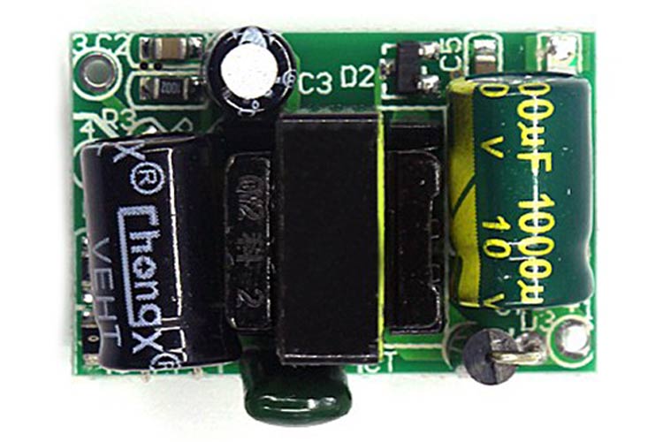
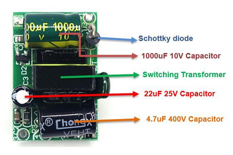
Overview of The 5V 700mA (3.5V) isolated SMPS
The 5V 700mA (3.5V) isolated Switch Power Supply Module has three electrolytic capacitors. A 1000uF 10V capacitor can be found near the output terminals and a 4.7uF 400V capacitor can be seen near the input terminal. A step-down transformer is situated at the center of the board. A 22uF 50V capacitor is soldered beside the transformer. Under the 4.7uF capacitor, a bridge rectifier diode labeled as MB6S is soldered on the top side of the board. A Schottky Diode can be found alongside the 1000uF 10V Capacitor.
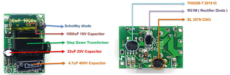
At the bottom side of the board, a single IC Chip labeled as THX208 -T 2019 is a switching power supply controller. An RS1M rectifier diode can be found at the bottom side of the board. An EL357NC943 Coupler IC can be found at the bottom side.
Working
An AC input is provided at the input terminal of the 5V 700mA (3.5W) Isolated switched power supply module. The MB6S diode bridge rectifier will convert the AC input to the DC voltage. The 4.7uF 400V capacitor is used to rectify the DC ripple and smoothen the DC output of the controller IC and the transformer. The primary side of the transformer is controlled by the THX208 switching power supply controller IC. The transformer is acting as an inductor here. A Zener diode is used to clamp the output voltage circuit and the fast-diode blocks the high spikes that are generated by the transformer’s leakage inductance.
The output from the transformer is rectified by the Schottky diode and a large 1000uF 10V capacitor, respectively. Whenever a perfect voltage is produced, the optocoupler that is EL357NC943 senses the line. Then it triggers the controller IC and isolates the secondary feedback part with the primary side controller. At the output terminal 5V, 700mA can be measured. But this is a Flyback Converter so the controller IC turns on the switching and waits for the response from the optocoupler. If the circuit is working fine, then the controller IC continues the switching, otherwise, it will skip the switching.
Applications
The 5V 700mA isolated power supply module can be used:
- Mobile chargers
- To power any circuits which require a 5V power supply
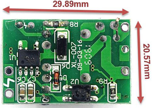
2D Model
The 2D model in this section consists of the module's dimensions in millimeters. This information can be used for designing custom footprints of the module, which can be used for PCB designing and CAD modelling.