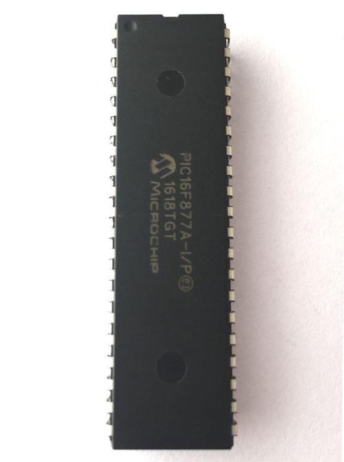
PIC16F877A Microcontroller
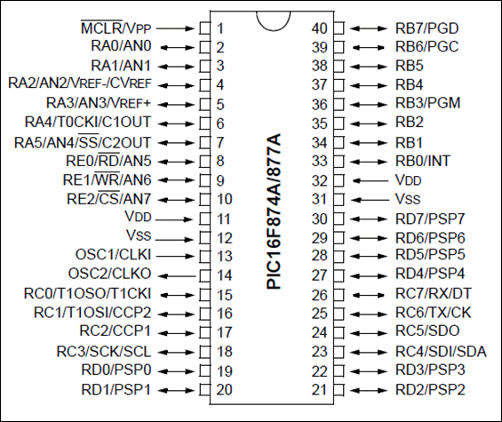
PIC16F877A Microcontroller Pinout Configuration
|
Pin Number |
Pin Name |
Description |
|
1 |
MCLR/Vpp |
MCLR is used during programming, mostly connected to programmer like PicKit |
|
2 |
RA0/AN0 |
Analog pin 0 or 0th pin of PORTA |
|
3 |
RA1/AN1 |
Analog pin 1 or 1st pin of PORTA |
|
4 |
RA2/AN2/Vref- |
Analog pin 2 or 2nd pin of PORTA |
|
5 |
RA3/AN3/Vref+ |
Analog pin 3 or 3rd pin of PORTA |
|
6 |
RA4/T0CKI/C1out |
4th pin of PORTA |
|
7 |
RA5/AN4/SS/C2out |
Analog pin 4 or 5th pin of PORTA |
|
8 |
RE0/RD/AN5 |
Analog pin 5 or 0th pin of PORTE |
|
9 |
RE1/WR/AN6 |
Analog pin 6 or 1st pin of PORTE |
|
10 |
RE2/CS/AN7 |
7th pin of PORTE |
|
11 |
Vdd |
Ground pin of MCU |
|
12 |
Vss |
Positive pin of MCU (+5V) |
|
13 |
OSC1/CLKI |
External Oscillator/clock input pin |
|
14 |
OSC2/CLKO |
External Oscillator/clock output pin |
|
15 |
RC0/T1OSO/T1CKI |
0th pin of PORT C |
|
16 |
RC1/T1OSI/CCP2 |
1st pin of POCTC or Timer/PWM pin |
|
17 |
RC2/CCP1 |
2nd pin of POCTC or Timer/PWM pin |
|
18 |
RC3/SCK/SCL |
3rd pin of POCTC |
|
19 |
RD0/PSP0 |
0th pin of POCTD |
|
20 |
RD1/PSPI |
1st pin of POCTD |
|
21 |
RD2/PSP2 |
2nd pin of POCTD |
|
22 |
RD3/PSP3 |
3rd pin of POCTD |
|
23 |
RC4/SDI/SDA |
4th pin of POCTC or Serial Data in pin |
|
24 |
RC5/SDO |
5th pin of POCTC or Serial Data Out pin |
|
25 |
RC6/Tx/CK |
6th pin of POCTC or Transmitter pin of Microcontroller |
|
26 |
RC7/Rx/DT |
7th pin of POCTC or Receiver pin of Microcontroller |
|
27 |
RD4/PSP4 |
4th pin of POCTD |
|
28 |
RD5/PSP5 |
5th pin of POCTD |
|
29 |
RD6/PSP6 |
6th pin of POCTD |
|
30 |
RD7/PSP7 |
7th pin of POCTD |
|
31 |
Vss |
Positive pin of MCU (+5V) |
|
32 |
Vdd |
Ground pin of MCU |
|
33 |
RB0/INT |
0th pin of POCTB or External Interrupt pin |
|
34 |
RB1 |
1st pin of POCTB |
|
35 |
RB2 |
2nd pin of POCTB |
|
36 |
RB3/PGM |
3rd pin of POCTB or connected to programmer |
|
37 |
RB4 |
4th pin of POCTB |
|
38 |
RB5 |
5th pin of POCTB |
|
39 |
RB6/PGC |
6th pin of POCTB or connected to programmer |
|
40 |
RB7/PGD |
7th pin of POCTB or connected to programmer |
PIC16F877A Features
|
PIC16F877A –Simplified Features |
|
|
CPU |
8-bit PIC |
|
Number of Pins |
40 |
|
Operating Voltage (V) |
2 to 5.5 V |
|
Number of I/O pins |
33 |
|
ADC Module |
8ch, 10-bit |
|
Timer Module |
8-bit(2), 16-bit(1) |
|
Comparators |
2 |
|
DAC Module |
Nil |
|
Communication Peripherals |
UART(1), SPI(1), I2C(1), MSSP(SPI/I2C) |
|
External Oscillator |
Up to 20Mhz |
|
Internal Oscillator |
Nil |
|
Program Memory Type |
Flash |
|
Program Memory (KB) |
14KB |
|
CPU Speed (MIPS) |
5 MIPS |
|
RAM Bytes |
368 |
|
Data EEPROM |
256 bytes |
Note: Complete technical details can be found in the PIC16F877A Datasheet linked at the bottom of this page.
Other PIC MCU’s
PIC12F508, PIC12F629, PIC12F683, PIC16F505, PIC16F628A, PIC16F676, PIC16F72, PIC16F873A, PIC16F876A, PIC16F886, PIC18F252, PIC18F25520, PIC18F452, PIC18F4520
PIC16F877A
This powerful (200 nanosecond instruction execution) yet easy-to-program (only 35 single word instructions) CMOS FLASH-based 8-bit microcontroller packs Microchip's powerful PIC® architecture into an 40 package and is upwards compatible with the PIC16C5X, PIC12CXXX and PIC16C7X devices. The PIC16F877A features 256 bytes of EEPROM data memory, self programming, an ICD, 2 Comparators, 8 channels of 10-bit Analog-to-Digital (A/D) converter, 2 capture/compare/PWM functions, the synchronous serial port can be configured as either 3-wire Serial Peripheral Interface (SPI™) or the 2-wire Inter-Integrated Circuit (I²C™) bus and a Universal Asynchronous Receiver Transmitter (USART).
How to Select your PIC Microcontroller
Microchip provides a waste verity of Microcontrollers from PIC family. Each MCU has its own advantage and disadvantage. There are many parameters that one has to consider before selecting a MCU for his project. The below points are just suggestions which might help one to select a MCU.
- If you are a beginner who is learning PIC then, selecting a MCU that has good online community support and wide applications will be a good choice. PIC16F877A and PIC18F4520 are two such MCUs
- Consider the operating voltage of your system. If they are 5V then select a 5V MCU some sensors or devices work and communicate on 3.3V in such case a 3.3V MCU can be selected
- If size and price is a limitation then you can choose small 8-pin MCUs like PIC12F508. These are also comparatively cheaper.
- Based on the sensors and actuators used in your project, verify which modules you might need in for MCU. For example is you are reading many Analog voltages then make sure PIC has enough ADC channels and supportive resolution. The details of all modules are given in the table above.
- If you project involves communication protocols like UART, SPI ,I2C, CAN etc make sure you PIC can support them. Some MCU can support more than one module of the same protocol
Programming PIC Microcontroller
PIC microcontroller can be programmed with different software's that is available in the market. There are people who still use Assembly language to program PIC MCUs. The below details is for most advanced and common software and compiler that has been developed by Microchip itself.
In order to program the PIC microcontroller we will need an IDE (Integrated Development Environment), where the programming takes place. A compiler, where our program gets converted into MCU readable form called HEX files. An IPE (Integrated Programming Environment), which is used to dump our hex file into our PIC MCUs.
IDE: MPLABX v3.35
IPE: MPLAB IPE v3.35
Compiler: XC8
Microchip has given all these three software for free. They can be downloaded directly from their official page. I have also provided the link for your convenience. Once downloaded install them on your computer. If you have any problem doing so you can post them on the comment below.
To dump or upload our code into PIC, we will need a device called PICkit 3. The PICkit 3 programmer/debugger is a simple, low-cost in-circuit debugger that is controlled by a PC running MPLAB IDE (v8.20 or greater) software on a Windows platform. The PICkit 3 programmer/debugger is an integral part of the development engineer's tool suite. In addition to this we will also need other hardware like Perf board or breadboard, Soldering station, PIC ICs, Crystal oscillators, capacitors etc.
Components associated with PIC
PICkit3, PIC Development Board, Crystal oscillators, capacitors, 12V Adapter, 7805 Voltage Regulator.
Detailed Features of PIC16F877A
|
PIC16F877A –Detailed Features |
|
|
CPU |
8-bit PIC |
|
Architecture |
8 |
|
Program Memory Size (Kbytes) |
14 |
|
RAM (bytes) |
368 |
|
EEPROM/HEF |
256/HEF |
|
Pin Count |
40 |
|
Max. CPU Speed (MHz) |
20 |
|
Peripheral Pin select (PPS) |
No |
|
Internal Oscillator |
No |
|
No. Of comparators |
2 |
|
No. Of Operational Amplifier |
0 |
|
No. Of ADC channels |
14 |
|
Max ADC Resolution (bits) |
10 |
|
ADC with Computation |
No |
|
Number of DAC Converter |
0 |
|
Max DAC resolution |
0 |
|
Internal Voltage Reference |
Yes |
|
Zero Cross Detect |
No |
|
No. Of 8-bit timers |
2 |
|
No. Of 16-bit Timers |
1 |
|
Signal Measurement Timer |
0 |
|
Hardware Limit Timer |
0 |
|
No. Of PWM outputs |
0 |
|
Max PWM resolution |
10 |
|
Angular Timer |
No |
|
Math Accelerator |
No |
|
No. Of UART module |
1 |
|
No. Of SPI Module |
1 |
|
No. Of I2C module |
1 |
|
No. Of USB Module |
0 |
|
Windowed Watchdog Timer (WWDT) |
No |
|
CRC/Scan |
No |
|
Numerically Controlled Oscillator |
0 |
|
Cap. Touch Channels |
11 |
|
Segment LCD |
0 |
|
Minimum Operating Temperature (*C) |
-40 |
|
Maximum Operating Temperature (*C) |
125 |
|
Minimum Operating Voltage (V) |
2 |
|
Maximum Operating Voltage (V) |
5.5 |
|
High Voltage Capable |
No |
Applications
- Multiple DIY Projects
- Very good choice if you are learning PIC
- Projects requiring Multiple I/O interfaces and communications
- Replacement for Arduino Module
- Ideal for more advanced level A/D applications in automotive, industrial, appliances and consumer applications.


