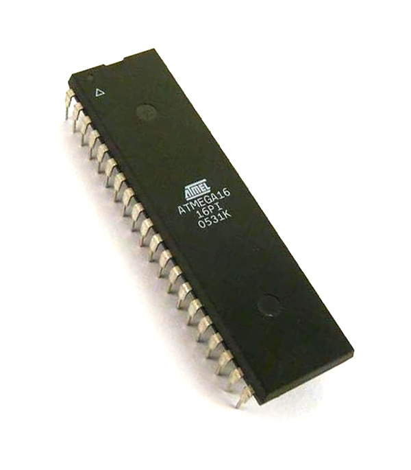
ATMega16 - 8-Bit AVR Microcontroller
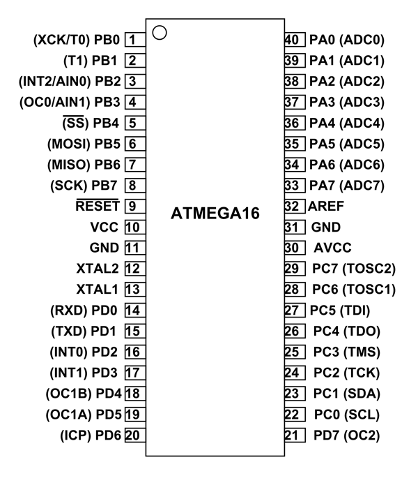
ATMEGA16 Pin Configuration
|
PIN NO. |
PIN NAME |
DESCRIPTION |
ALTERNATE FUNCTION |
|
1 |
PB0(XCK/T0) |
Pin 0 of PORTB |
T0( Timer0 External Counter Input) XCK ( USART External Clock I/O) |
|
2 |
PB1(T1) |
Pin 1 of PORTB |
T1(Timer1 External Counter Input) |
|
3 |
PB2(INT2/AIN0) |
Pin 2 of PORTB |
AIN0(Internal Analog Comparator Positive Input)
INT2( External Interrupt 2 Input) |
|
4 |
PB3(OC0/AIN1) |
Pin 3 of PORTB |
AIN1(Internal Analog Comparator Negative Input)
OC0 (Timer0 Output Compare Match Output) or PWM output
|
|
5 |
PB4(SS ) |
Pin 4 of PORTB |
SS (SPI Slave Select Input). This pin is low when controller acts as slave.
[Serial Peripheral Interface (SPI) for programming] |
|
6 |
PB5(MOSI) |
Pin 5 of PORTB |
MOSI (Master Output Slave Input). When controller acts as slave, the data is received by this pin. [Serial Peripheral Interface (SPI) for programming] |
|
7 |
PB6(MISO) |
Pin 6 of PORTB |
MISO (Master Input Slave Output). When controller acts as slave, the data is sent to master through this pin.
[Serial Peripheral Interface (SPI) for programming] |
|
8 |
PB7(SCK) |
Pin 7 of PORTB |
SCK (SPI Bus Serial Clock). This is the clock shared between this controller and other system for accurate data transfer. [Serial Peripheral Interface (SPI) for programming] |
|
9 |
RESET |
Reset Pin (Active Low Reset) |
|
|
10 |
VCC |
Connected to +5V |
|
|
11 |
GND |
Connected to GROUND |
|
|
12 |
XTAL2 |
Connected to Crystal Oscillator |
|
|
13 |
XTAL1 |
Connected to Crystal Oscillator |
|
|
14 |
PD0(RXD) |
Pin 0 of PORTD |
RXD (USART Input Pin)
[USART Serial Communication Interface can be used for programming] |
|
15 |
PD1(TXD) |
Pin 1 of PORTD |
TXD (USART Output Pin)
[USART Serial Communication Interface can be used for programming] |
|
16 |
PD2(INT0) |
Pin 2 of PORTD |
External Interrupt INT0 |
|
17 |
PD3(INT1) |
Pin 3 of PORTD |
External Interrupt INT1 |
|
18 |
PD4(OC1B) |
Pin 4 of PORTD |
OC1B (Timer Output Compare Match Output) or PWM output |
|
19 |
PD5(OC1A) |
Pin 5 of PORTD |
OC1A (Timer Output Compare Match Output) or PWM output |
|
20 |
PD6(ICP) |
Pin 6 of PORTD |
Timer/Counter1 Input Capture Pin |
|
21 |
PD7 (OC2) |
Pin 7 of PORTD |
Timer/Counter2 Output Compare Match Output |
|
22 |
PC0 (SCL) |
Pin 0 of PORTC |
TWI Interface |
|
23 |
PC1 (SDA) |
Pin 1 of PORTC |
TWI Interface |
|
24 |
PC2 (TCK) |
Pin 2 of PORTC |
JTAG Interface |
|
25 |
PC3 (TMS) |
Pin 3 of PORTC |
JTAG Interface |
|
26 |
PC4 (TDO) |
Pin 4 of PORTC |
JTAG Interface |
|
27 |
PC5 (TDI) |
Pin 5 of PORTC |
JTAG Interface |
|
28 |
PC6 (TOSC1) |
Pin 6 of PORTC |
Timer Oscillator Pin 1 |
|
29 |
PC7 (TOSC2) |
Pin 7 of PORTC |
Timer Oscillator Pin 2 |
|
30 |
AVcc |
Vcc for Internal ADC Converter |
|
|
31 |
GND |
GROUND |
|
|
32 |
AREF |
Analog Reference Pin for ADC |
|
|
33 |
PA7 (ADC7) |
Pin 7 of PORTA |
ADC (Analog to Digital Converter) Channel 7 |
|
34 |
PA6 (ADC6) |
Pin 6 of PORTA |
ADC (Analog to Digital Converter) Channel 6 |
|
35 |
PA5 (ADC5) |
Pin 5 of PORTA |
ADC (Analog to Digital Converter) Channel 5 |
|
36 |
PA4 (ADC4) |
Pin 4 of PORTA |
ADC (Analog to Digital Converter) Channel 4 |
|
37 |
PA3 (ADC3) |
Pin 3 of PORTA |
ADC (Analog to Digital Converter) Channel 3 |
|
38 |
PA2 (ADC2) |
Pin 2 of PORTA |
ADC (Analog to Digital Converter) Channel 2 |
|
39 |
PA1 (ADC1) |
Pin 1 of PORTA |
ADC (Analog to Digital Converter) Channel 1 |
|
40 |
PA0 (ADC0) |
Pin 0 of PORTA |
ADC (Analog to Digital Converter) Channel 0 |
ATMEGA16 Features
|
ATMEGA16 – Simplified Features |
|
|
CPU |
8-bit AVR |
|
Number of Pins |
40 |
|
Operating Voltage |
For ATMEGA16:+4.5 to +5.5 V (+5.5V being absolute maximum) For ATMEGA16L:+2.7 to 5.5V(+5.5V being absolute maximum) |
|
Number of Input/output pins |
32 |
|
Communication Interface |
JTAG Interface(24,25,26,27 PINS)[Can be used for programming this controller] SPI Serial Interface(5,6,7,8 PINS) [Can be used for programming this controller] Programmable Serial USART(14,15 PINS) [Can be used for programming this controller] Two-wire Serial Interface(22,23 PINS)[Can be used to connect peripheral devices like sensors and servos] |
|
ADC Module |
8 channels , 10-bit resolution ADC |
|
Timer Module |
Two 8-bit counters, One 16-bit counter [Total three] |
|
Analog Comparators |
1 |
|
DAC Module |
Nil |
|
PWM channels |
4 |
|
External Oscillator |
0-8MHz for ATMEGA16L 0-16MHz for ATMEGA16 |
|
Internal Oscillator |
0-8MHz Calibrated Internal Oscillator |
|
Program Memory Type |
Flash |
|
Program Memory |
16Kbytes[10000 write/erase cycles] |
|
CPU Speed |
16 MIPS |
|
RAM Bytes |
1KBytes |
|
Data EEPROM |
512 Bytes |
|
Watchdog Timer |
Yes |
|
Power Save Modes |
Six Modes[Idle, ADC Noise Reduction, Power-save, Power-down, Standby and Extended Standby] |
|
Operating Temperature |
-55°C to +125°C(+125 being absolute maximum, -55 being absolute minimum) |
ATMEGA16 Electrical Characteristics
- Maximum voltage on any pin except RESET : -0.5V to ( Vcc + 0.5)V
- Maximum voltage on RESET pin : -0.5V to +13.0V
- Maximum DC current allowed through any I/O pin : 40mA
- Maximum DC current through Vcc and GND pins: 200mA
- Storage temperature:-65ºC to +150ºC
ATMEGA16 Replacements
ATMEGA32, ATMEGA8535
ATMEGA16 Alternatives
Where to use ATMEGA16
ATMEGA16 microcontroller is one of the popular controllers in AVR series. With its features and purchase cost, it became one of favorite controller for both hobbyists and engineers. ATMEGA16 programming is similar to any other AVR controller. It is particularly a clone to ATMEGA32 except for the memory. Although it has only half the memory of ATMEGA32, it is still more than enough to satisfy most EMBEDDED SYSTEMS.
ATMEGA16 has also sleep modes. The modes can be triggered at desired times to save power. With various sleep modes on board ATMEGA16 can work on MOBILE EMBEDDED SYSTEMS.
ATMEGA16 has 32 programmable Input/output pins, with them ATMEGA16 can interface many peripherals easily.
ATMEGA16 has also programmable Watchdog Timer with Separate On-chip Oscillator. With this Watchdog timer to reset under error the controller can be used on applications where human interference in minimal.
How to Use ATMEGA16 Microcontroller
As mentioned earlier ATMEGA16 is similar to any other microcontroller and in particular ATMEGA32. It basically can perform any function that is performed by ATMEGA32. Similar to them it is not Plug and Play digital ICs. For working of ATMEGA16, first we need to save the program HEX code in ATMEGA16 FLASH MEMORY. After executing this code, ATMEGA16 creates the desired response.
Entire process of using an ATMEGA16 goes like this:
- List the functions to be executed by ATMEGA16 in a paper.
- Next download program developing application (called IDE) for AVR controllers
(Usually Atmel Studio 6.2 for Windows7,
Atmel Studio 7 for Windows10 [ http://www.microchip.com/avr-support/avr-and-sam-downloads-archive ])
- Write the functions in ‘C’ language in IDE.
- After writing the program compile it in IDE. This eliminates errors.
- Make IDE application to generate HEX file for the written program after compiling.
- Choose the programming device (usually SPI programmer made for AVR controllers) which establishes communication between your Personal Computer and ATMEGA16.
- Run the HEX file burning software which is given for the chosen programming device.
- Choose the appropriate program HEX file in the programmer software.
- Burn the HEX file (Which contains program in the form of HEX code) in ATMEGA16 flash memory using this program.
Disconnect the programmer, connect the appropriate peripherals for the controller and power the system. With this ATMEGA16 executes the program and provides the response written in the saved program.
Applications
There are many of applications for ATMEGA16 microcontrollers.
- Hobbyists applications
- Engineers design
- Temperature control systems
- Analog signal measuring and manipulations.
- Embedded systems like coffee machine, vending machine.
- Motor control systems.
- Digital signal processing.
- Peripheral Interface system.
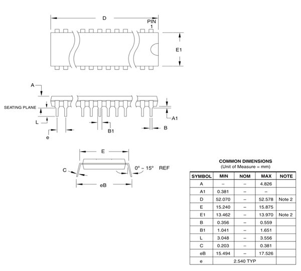
2D Model