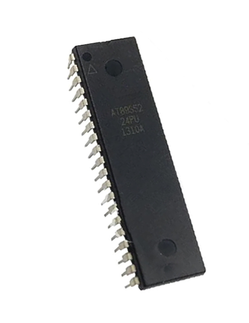
AT89S52 8-bit Microcontroller
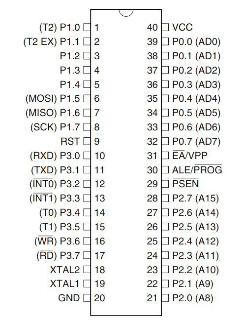
AT89S52 Pin Configuration
|
Pin Number |
Pin Name |
Description |
|
1 |
P1.0 (T2) |
Timer/Counter or 0th GPIO pin of PORT 1 |
|
2 |
P1.1 (T2.EX) |
Timer/Counter/External Counter or 1st GPIO pin of PORT 1 |
|
3 |
P1.2 |
2nd GPIO pin of PORT 1 |
|
4 |
P1.3 |
3rd GPIO pin of PORT 1 |
|
5 |
P1.4 |
4th GPIO pin of PORT 1 |
|
6 |
P1.5 (MOSI) |
MOSI for in System Programming or 5th GPIO pin of PORT 1 |
|
7 |
P1.6 (MISO) |
MISO for in System Programming or 6th GPIO pin of PORT 1 |
|
8 |
P1.7 (SCK) |
SCK for in System Programming or 7th GPIO pin of PORT 1 |
|
9 |
RST |
Making this pin high will reset the Microcontroller |
|
10 |
P3.0 (RXD) |
RXD Serial Input or 0th GPIO pin of PORT 3 |
|
11 |
P3.1 (TXD) |
TXD Serial Output or 1st GPIO pin of PORT 3 |
|
12 |
P3.2 (INT0’) |
External Interrupt 0 or 2nd GPIO pin of PORT 3 |
|
13 |
P3.3 (INT1’) |
External Interrupt 1 or 3rd GPIO pin of PORT 3 |
|
14 |
P3.4 (T0) |
Timer 0 or 4th GPIO pin of PORT 3 |
|
15 |
P3.5 (T1) |
Timer 1 or 5th GPIO pin of PORT 3 |
|
16 |
P3.6 (WR’) |
Memory Write or 6th GPIO pin of PORT 3 |
|
17 |
P3.7 (RD’) |
Memory Read or 7th GPIO pin of PORT 3 |
|
18 |
XTAL2 |
External Oscillator Output |
|
19 |
XTAL1 |
External Oscillator Input |
|
20 |
GND |
Ground pin of MCU |
|
21 |
P2.0(A8) |
0th GPIO pin of PORT 2 |
|
22 |
P2.1 (A9) |
1st GPIO pin of PORT 2 |
|
23 |
P2.2 (A10) |
2nd GPIO pin of PORT 2 |
|
24 |
P2.3 (A11) |
3rd GPIO pin of PORT 2 |
|
25 |
P2.4 (A12) |
4th GPIO pin of PORT 2 |
|
26 |
P2.5 (A13) |
5th GPIO pin of PORT 2 |
|
27 |
P2.6 (A14) |
6th GPIO pin of PORT 2 |
|
28 |
P2.7 (A15) |
7th GPIO pin of PORT 2 |
|
29 |
PSEN’ |
Program store Enable used to read external program memory |
|
30 |
ALE / PROG’ |
Address Latch Enable / Program Pulse Input |
|
31 |
EA’ / VPP |
External Access Enable / Programming enable Voltage |
|
32 |
P0.7 (AD7) |
Address / Data pin 7 or 7th GPIO pin of PORT 0 |
|
33 |
P0.6 (AD6) |
Address / Data pin 6 or 6th GPIO pin of PORT 0 |
|
34 |
P0.5 (AD5) |
Address / Data pin 5 or 5th GPIO pin of PORT 0 |
|
35 |
P0.4 (AD4) |
Address / Data pin 4 or 4th GPIO pin of PORT 0 |
|
36 |
P0.3 (AD3) |
Address / Data pin 3 or 3rd GPIO pin of PORT 0 |
|
37 |
P0.2 (AD2) |
Address / Data pin 2 or 2nd GPIO pin of PORT 0 |
|
38 |
P0.1 (AD1) |
Address / Data pin 1 or 1st GPIO pin of PORT 0 |
|
39 |
P0.0 (AD0) |
Address / Data pin 0 or 0th GPIO pin of PORT 0 |
|
40 |
VCC |
Positive pin of MCU (+5V) |
AT89S52 Microcontroller Features
|
AT89S52 –Simplified Features |
|
|
CPU |
8-bit PIC |
|
Number of Pins |
40 |
|
Operating Voltage (V) |
4 to 5.5 V |
|
Number of Programmable I/O pins |
32 |
|
ADC Module |
Nil |
|
Timer Module |
16-bit(1) |
|
Comparators |
Nil |
|
DAC Module |
Nil |
|
Communication Peripherals |
UART(1) |
|
External Oscillator |
Up to 23Mhz |
|
Internal Oscillator |
Nil |
|
Program Memory Type |
Flash |
|
Program Memory (KB) |
8KB |
|
CPU Speed (MIPS) |
- |
|
RAM Bytes |
256 x 8-bit |
|
Data EEPROM |
Nil |
Note: More detailed Features can be found in the AT89S52 Microcontroller linked at the bottom of this page.
Other Atmel 8-bit MCU’s
AT89C51, Atmega8A, Attiny1614, Atmega328
Brief Intro to AT89S52 Microcontroller
The AT89S52 comes from the popular 8051 family of Atmel Microcontrollers. It is an 8-bit CMOS microcontroller with 8K as Flash memory and 256 bytes of RAM. Since it is similar to the trust worthy 8051 architecture, these microcontrollers are as per industry standard. It has 32 I/O pins comprising of three 16-bit timers, external interrupts, full-duplex serial port, on-chip oscillator and clock circuitry.
The Microcontroller also has Operating mode, Idle Mode and Power down mode which makes it suitable for battery operated applications. Few considerable drawback of the microcontroller is that it does not have in-built ADC and does not support SPI or I2C protocols. However you can utilise external modules for the same.
Programming AT89S52 Microcontroller
Atmel microcontroller can be programmed with different software's that is available in the market. Arduino, Keil uVision are the most used platforms to name a few. If you are planning on serious programming and expansion with community support then Keil is recommended.
In order to program the Atmel microcontroller we will need an IDE (Integrated Development Environment), where the programming takes place. A compiler, where our program gets converted into MCU readable form called HEX files. An IPE (Integrated Programming Environment), which is used to dump our hex file into our MCUs.
IDE: Keil uVision IDE
Programming Hardware: USB In-circuit programmer (USBASP)
Programmer: USBASP
To dump or upload our code into Atmel IC we need a programmer, the most commonly used programmer is the USBASP which has to be purchased separately. Also simulating you program on software before trying it on hardware will save a lot of time. So you can use software like ISIS proteus from Labcenter to simulate you r programs.
A bare minimum circuit to program an Atmel microcontroller is shown below.
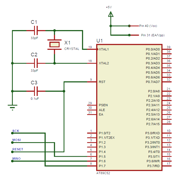
Components associated: USBASP, Crystal oscillators, capacitors, 12V Adapter, 7805 Voltage Regulator.
Detailed Features
|
AT89S52 – Detailed Features |
|
|
CPU |
8-bit 8051 family |
|
Architecture |
8 |
|
Program Memory Size (Kbytes) |
8K Flash |
|
RAM (bytes) |
256 |
|
EEPROM/HEF |
Nil |
|
Pin Count |
40 |
|
Max. CPU Speed (MHz) |
33 |
|
Peripheral Pin select (PPS) |
No |
|
Internal Oscillator |
No |
|
No. Of comparators |
2 |
|
No. Of Operational Amplifier |
0 |
|
No. Of ADC channels |
Nil |
|
Max ADC Resolution (bits) |
NA |
|
ADC with Computation |
No |
|
Number of DAC Converter |
0 |
|
Max DAC resolution |
0 |
|
Internal Voltage Reference |
NA |
|
Zero Cross Detect |
No |
|
No. Of 8-bit timers |
0 |
|
No. Of 16-bit Timers |
3 |
|
Signal Measurement Timer |
0 |
|
Hardware Limit Timer |
0 |
|
No. Of PWM outputs |
0 |
|
Max PWM resolution |
NA |
|
Angular Timer |
No |
|
Math Accelerator |
No |
|
No. Of UART module |
1 |
|
No. Of SPI Module |
0 |
|
No. Of I2C module |
0 |
|
No. Of USB Module |
0 |
|
Windowed Watchdog Timer (WWDT) |
No |
|
CRC/Scan |
No |
|
Numerically Controlled Oscillator |
0 |
|
Cap. Touch Channels |
NA |
|
Segment LCD |
0 |
|
Minimum Operating Temperature (*C) |
-55 |
|
Maximum Operating Temperature (*C) |
125 |
|
Minimum Operating Voltage (V) |
4 |
|
Maximum Operating Voltage (V) |
5.5 |
|
High Voltage Capable |
No |
How to Select your Atmel Microcontroller
Microchip provides a vast variety of Microcontrollers from PIC family and Atmel Family. Their collection has just piled up after Microchip has acquired Atmel. Each MCU has its own advantage and disadvantage. There are many parameters that one has to consider before selecting a MCU for his/her project. The below points are just suggestions which might help one to select a MCU.
- If you are a beginner who is learning Microcontroller, then selecting a MCU that has good online community support and wide applications will be a good choice. For Atmel AT89S52 or ATmega328 will be a good choice.
- Consider the operating voltage of your system. If they are 5V then select a 5V MCU some sensors or devices work and communicate on 3.3V in such case a 3.3V MCU can be selected
- If size and price is a limitation then you can choose small 8-pin MCUs like Attiny1614. These are also comparatively cheaper.
- Based on the sensors and actuators used in your project, verify which modules you might need in for MCU. For example is you are reading many Analog voltages then make sure MCU has enough ADC channels and supportive resolution. The details of all modules are given in the table above.
- If you project involves communication protocols like UART, SPI ,I2C, CAN etc make sure you MCU can support them. Some MCU can support more than one module of the same protocol
Applications
- Multiple DIY Projects
- Very good choice if you are learning ATmel
- Projects requiring Multiple I/O interfaces and communications
- Replacement for Arduino Module
- Ideal for more advanced level A/D applications in automotive, industrial, appliances and consumer applications.
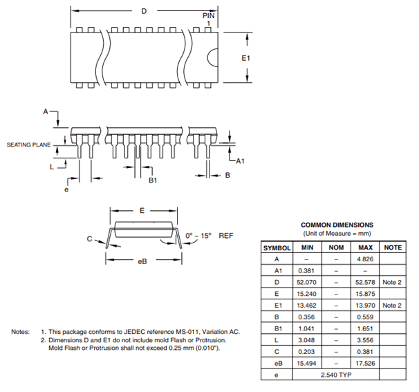
2D Model (PSDIP)