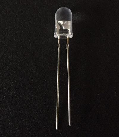
IR LED (Infrared LED)
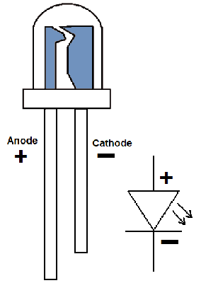
Pin Configuration
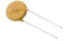
The IR LED or Infrared LED has polarity i.e.it has a positive and negative pin. The pin which is long is the positive pin (anode) and the pin which is short is the negative pin (cathode) as shown in the above IR LED pinout.
Technical Specifications
- Forward current (IF) is 100mA (normal condition) and 300mA (max.)
- 1.5A of surge forward current
- 1.24v to 1.4v of forward voltage
- Temperature for storage and operation varies from -40 to 100 ℃
- Soldering Temperature should not exceed 260 ℃
- Power Dissipation of 150mW at 25℃ (free air temperature) or below
- Spectral bandwidth of 45nm
- Viewing angle is 30 to 40 degree
Features
- High Reliability
- Excessive radiant intensity
- Forward voltage is low
- Having lead spacing of 2.54mm
- Maximum wavelength is 940nm
- Pb free
- RoHS certified
- Easy to use with breadboard or perf board
- Package type is T-1 3/4
Note: Complete technical information can be found in the IR LED Datasheet, linked at the bottom of this page.
Brief Description
An IR LED is a specially designed LED which transmits infrared rays. These rays are not able to be seen by the human eyes as it’s not in the range of human visible electromagnetic radiation spectrum. We can only see light rays from violet to red whose wavelength travels from 380 (violet light) to 750nm (red light).
The IR LED is same aspect as the normal LED. IR LED stands for “Infrared Light Emitting Diode”, they allows to emit light with the wavelength of up to 940nm, which is the infrared range of electromagnetic radiation spectrum. The wavelength range varies from 760nm to 1mm. These are mostly use in the remote control of TV’s, cameras and different types of electronic instruments. The semiconductor material used to make these LEDs are gallium arsenide or aluminum arsenide. Mostly used in IR sensor as it is the combination of IR receiver and IR transmitter (IR LED).
Where to use?
IR LED is used in various daily used electronic appliances. As in the remote of the television, infrared cameras, transmission systems. We can make various projects, sensor using the IR LED like obstacle detector, visitor-counter and line-followers. An Infrared LED looks same as normal LED, but human eye is not capable of seeing the IR light as it’s beyond our visible electromagnetic spectrum. We are only able to see a light having a wavelength ranges 380 to 750nm. You can see an IR light through your phone camera, night-vision, and, etc.
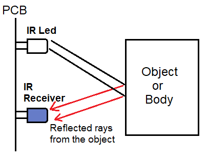
How to use?
The most common use of this LED is in IR sensor, with companion to IR receiver. An IR sensor works as it sends IR signal through the IR transmitter and receives through IR receiver. If we placed an object near to the IR sensor the LED connected to the sensor goes high.
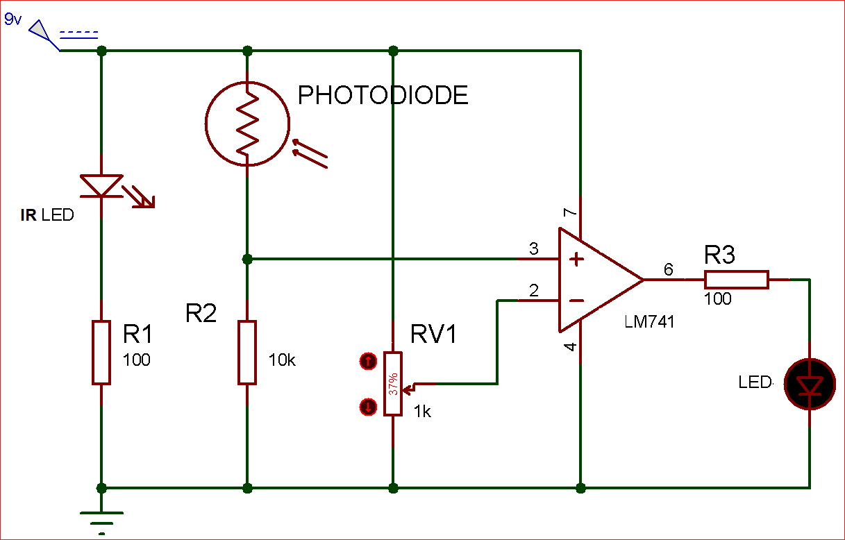
As in the circuit below, you can adjust the sensing strength through the potentiometer. The photodiode here works as the IR receiver which receives infrared rays of Infrared LED. The op-amp LM741 used to compare the voltage through the inverting and non-inverting terminal, as the voltage at non-inverting terminal increase than the inverting terminal it gives power to the LED connected in the circuit which means there is an object in front of IR sensor or in the viewing angle of it.
Applications
- Infrared applied systems
- Transmission system
- Optoelectronic switch
- Infrared remote control equipment’s
- Smoke detector
- IOT (internet of things) application
- Industrial equipment’s
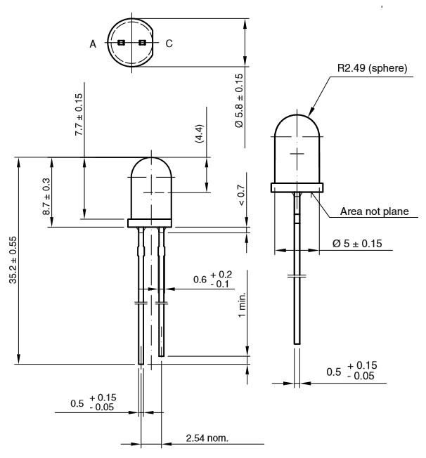
2D-Model and Dimensions