TM1650 - LED Driver with ASIC Keyboard Scanning
TM1650 is a LED driver for controlling LEDs with a keyboard scanning interface. It has an Integrated MCU Input and output control digital interface, data latch, LED drive, keyboard scanning, brightness adjustment, and other functionalities built into it. TM1650 has stable performance and quality. It is suitable for 24 hours long-term applications.
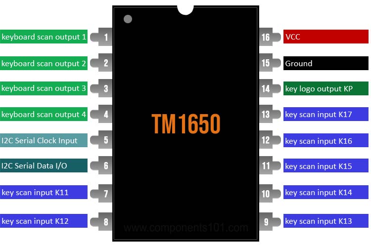
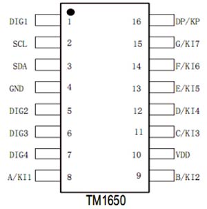
TM1650 Pinout Configuration
|
Pin Name |
Description |
|
DIG1 |
LED segment drive output 1 / keyboard scan output 1 |
|
DIG2 |
LED segment drive output 2 / keyboard scan output 2 |
|
DIG3 |
LED segment drive output 3 / keyboard scan output 3 |
|
DIG4 |
LED segment drive output 4 / keyboard scan output 4 |
|
SCL |
I2C Serial Clock Input |
|
SDA |
I2C Serial Data Input/Output |
|
A/K11 |
LED segment drive output A/key scan input K11 |
|
B/K12 |
LED segment drive output B/key scan input K12 |
|
C/K13 |
LED segment drive output C/key scan input K13 |
|
D/K14 |
LED segment drive output D/key scan input K14 |
|
E/K15 |
LED segment drive output E/key scan input K15 |
|
F/K16 |
LED segment drive output F/key scan input K16 |
|
G/K17 |
LED segment drive output G/key scan input K17 |
|
DP/KP |
LED segment output DP/keyboard logo output KP |
|
GND |
Ground |
|
VDD |
VCC of Supply |
Features & Specifications
- Two display modes: 8-segment × 4 digits and 7-segment × 4 digits
- Segment drive current is greater than 25mA,
- Provide 8-level brightness control
- Keyboard scanning: 7×4bit internal integrated transistor driver
- High-speed two-wire serial interface
- Built-in clock oscillation circuit
- Built-in power-on reset circuit
- Support 2.8V-5.5V power supply voltage
- Provide DIP16 and SOP16 packages
Note: Complete technical details can be found in the TM1650 IC datasheet given at the end of this page.
TM1650 Equivalent ICs
MBI5026GD, CD4511, MAX6945, MAX7221
Where to use TM1650 Display Keypad Driver IC
This is a very cheap and versatile device that can be used in many different applications. It can be used in BAR-Graph Display, Industrial Control, LED Matrix Display, and more; the devices include a 150μA low-power shutdown mode, 8 channel brightness control, a scan-limit register that allows the user to display from 1 to 8 digits, and a test mode that forces all LEDs on referring to the datasheet of the TM1650 for more information. The pinout for the TM1650 IC is shown below-
The TM1650 uses a 2-wire I2C serial transmission protocol for communication. Start signal: Keep SCL at "1" level, and SDA jumps from "1" to "0", which is regarded as a start signal. Such as End signal: Keep SCL at "1" level, and SDA jumps from "0" to "1", which is regarded as an end signal. If this communication is normal, the chip will take the initiative to pull SDA low after the 8th falling edge of the serial communication clock. Until inspection, it is detected that SCL has a rising edge, and SDA is released to the input state Write "1": keep SDA at "1" level, SCL jumps from "0" to "1", and then from "1" to "0", it is regarded as writing 1. Keeping SDA at "0" level, SCL jumps from "0" to "1", and then from "1" to "0", it is regarded as writing a 0. The transmission format of one byte of data is shown in Figure 4, when the data is sent, the MSB comes first, and the LSB comes after. The data of the microprocessor passes through the two-wire bus the interface communicates with TM1650. When SCL is high when inputting data, the signal on SDA must remain unchanged; only the signal on SCL and the signal on SDA can only change when the clock signal is low. The start condition of data input is when SCL is high, SDA changes from high to Low.
How to use the TM1650 IC
Though the datasheet says it uses an I2C interface but this IC can be driven without an I2C interface and its recommended to do so because first of all this IC does not provide any I2C address, which means you cannot drive more than one I2C device on the I2C bus, a basic schematic of TM1650 with a keypad is shown below.
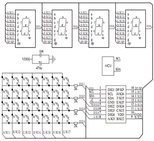
As you can clearly see that this device is made to control with a matrix keyboard that can be used to control the TM1650 IC. Other than that, this IC can be controlled with the help of an Arduino, to do so you can use the TM16XX library by maxint-rd from GitHub, this library will allow you to control the TMS1650 IC with any pin on the Arduino.
Applications
- household products
- Set-Top boxes
- Air conditioning
- DVD / VCD
- Display Applications
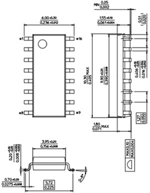
2D Model and Dimensions
If you are designing a PCB or Perf board with this component, then the following picture from the Datasheet will be useful to know its package type and dimensions.