4x4 Keypad Module
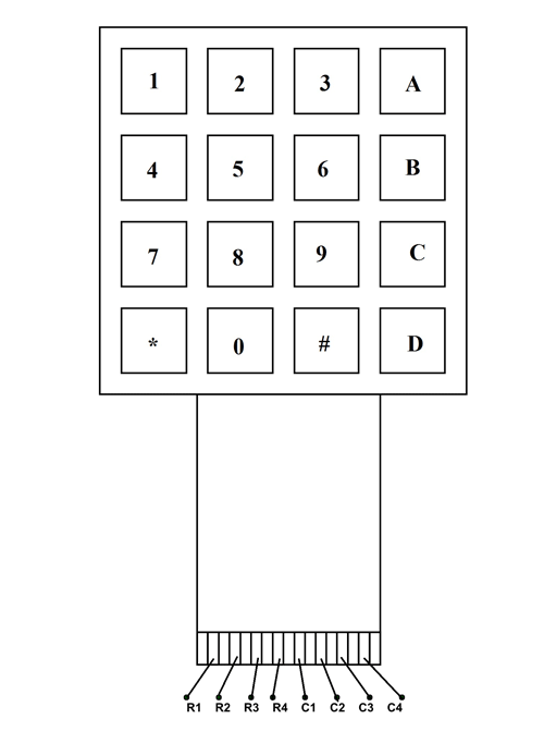
4X4 KEYPAD Pin Configuration
4X4 KEYPAD MODULES are available in different sizes and shapes. But they all have same pin configuration. It is easy to make 4X4 KEYPAD by arranging 16 buttons in matrix formation by yourself.
|
Pin Number |
Description |
|
ROWS |
|
|
1 |
PIN1 is taken out from 1st ROW |
|
2 |
PIN2 is taken out from 2nd ROW |
|
3 |
PIN3 is taken out from 3rd ROW |
|
4 |
PIN4 is taken out from 4th ROW |
|
COLUMN |
|
|
5 |
PIN5 is taken out from 1st COLUMN |
|
6 |
PIN6 is taken out from 2nd COLUMN |
|
7 |
PIN7 is taken out from 3rd COLUMN |
|
8 |
PIN8 is taken out from 4th COLUMN |
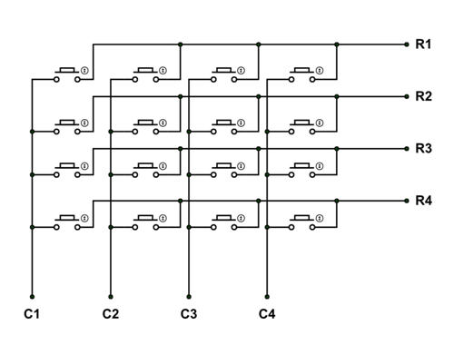
As given in above table, a 4X4 KEYPAD will have EIGHT TERMINALS. In them four are ROWS of MATRIX and four are COLUMNS of MATRIX. These 8 PINS are driven out from 16 buttons present in the MODULE. Those 16 alphanumeric digits on the MODULE surface are the 16 buttons arranged in MATRIX formation.
The internal structure of 4X4 KEYPAD MODULE is shown below.
4X4 KEYPAD MODULE Features and Specifications
- Maximum Voltage across EACH SEGMENT or BUTTON: 24V
- Maximum Current through EACH SEGMENT or BUTTON: 30mA
- Maximum operating temperature: 0°C to + 50°C
- Ultra-thin design
- Adhesive backing
- Easy interface
- Long life.
Note: Complete technical information can be found in the 4x4 Keypad Module Datasheet linked at the bottom of this page.
Where 4X4 KEYPAD MODULE is Used?
4X4 KEYPAD MODULE is used for many kind of applications. Few are:
Case1: When easy to use INPUT device is needed. For control systems or embedded systems there will be a time where human interaction is needed. Like a coffee machine needs choice selection. In those cases using 4X4 KEYPAD MODULE is best solution.
Case2: Input module can only have few pins. If certain applications are developed of processors with few pins then that system cannot afford to provide more pins to INPUT DEVICE. At that time using KEYPAD MODULE is ideal, as it can give 16 key inputs for using 8 terminals.
Case3: For professional look. Using KEYPAD MODULE can give more professional view to the system than other key INPUT DEVICES.
How to Use 4X4 KEYPAD MODULES
Using KEYPAD MODULE is little tricky. As 16 keys are connected in matrix formation the module is a little complex to use. The module gives only 8 pins as a way for interacting with 16 buttons.
We are going to explain how to use the KEYPAD MODULE in a simple way step by step:
Consider we have connected the KEYPAD MODULE to a microcontroller.
STEP1: First set all ROWS to OUTPUT and set them at +5V. Next set all COLUMNS as INPUT to sense the HIGH logic. Now consider a button is pressed on keypad. And that key is at 2ND COLUMN and 3rd ROW.
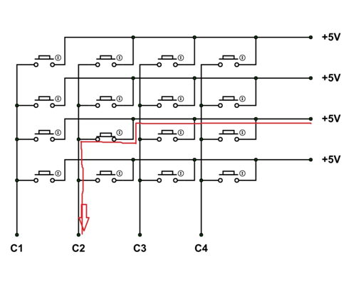
With the button being pressed the current flows as shown in figure. With that a voltage of +5V appears at terminal C2. Since the COLUMN pins are set as INPUTS, the controller can sense C2 going high. The controller can be programmed to remember that C2 going high and the button pressed is in C2 COLUMN.
STEP2: Next set all COLUMNS to OUTPUT and set them at +5V. Next set all ROWS as INPUT to sense the HIGH logic. Since the key pressed is at 2ND COLUMN and 3rd ROW. The current flows as shown below.
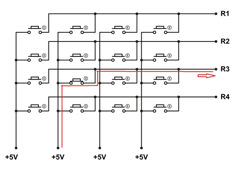
With that current flow a positive voltage of +5V appears at R3 pin. Since all ROWS are set as INPUTS, the controller can sense +5V at R3 pin. The controller can be programmed to remember the key being pressed at third ROW of KEYPAD MATRIX.
From previous step, we have known the COLUMN number of key pressed and now we know ROW number. With that we can match the key being pressed. We can take the key INPUT provided by this way for 4X4 KEYPAD MODULE.
Applications
- Security systems.
- Vending machines.
- Industrial machines.
- Engineering systems.
- Measuring instruments.
- Data entry for Embedded Systems
- Hobby projects.
- Basically any where INPUT device is needed.
2D Model
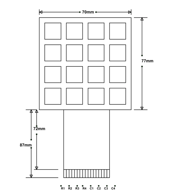
All measurements are given in millimeters.
