TLP521 Series Optocoupler with GaAs IR-LED & Photo-Transistor
The Toshiba TLP521-1 consists of a photo-transistor optically coupled to a gallium arsenide infrared emitter diode. This device can be used for applications where galvanic isolation is necessary, like Switch Mode Power Supply, relay driver board, etc.
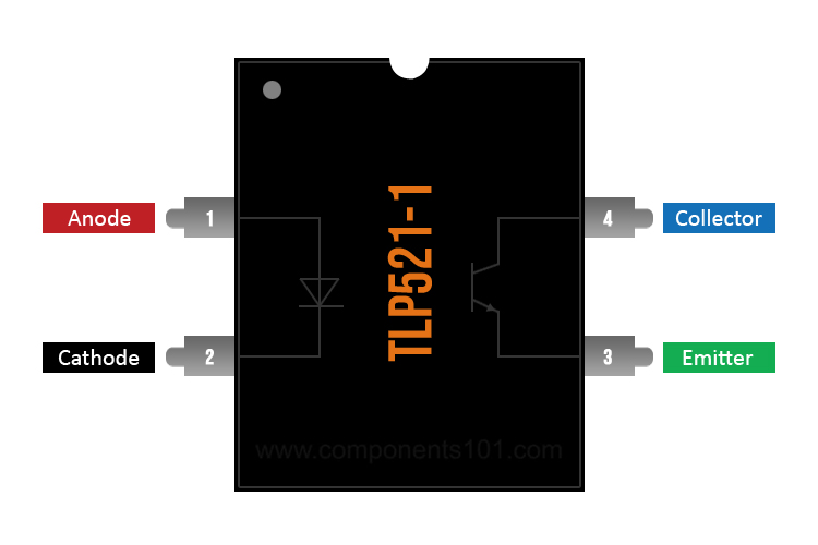
TLP521 Pinout Configuration
|
Pin Number |
Pin Name |
Description |
|
1 |
Anode |
Anode pin of the IR LED. Connected to logic input |
|
2 |
Cathode |
Cathode pin of the IR LED. Connected to ground |
|
3 |
Emitter |
Cathode pin of the IR LED. Connected to ground |
|
4 |
Collector |
Collector pin of the Transistor. Provides logical output |
Features & Specifications
- Input Diode Forward Voltage: 1.25V
- Reverse Voltage 5V
- Emitter-Collector Voltage 7V
- Isolated Voltage 2500 Vrms
- Collector-Emitter Voltage: 55V (max)
- Collector Current: 50mA (max)
- Cut-off frequency: 80 kHz
- Rise Time: 2us
- Fall Time: 3us
- Junction Temperature 125 C
- Total device Dissipation 150mW
- Available in 4-pin, 8-pin, and 16-pin DIP through hole package.
Note: More details can be found in the TLP521 datasheet given at the end of this page.
TLP521 Equivalent Optocouplers
General Description of TLP521 Optocoupler
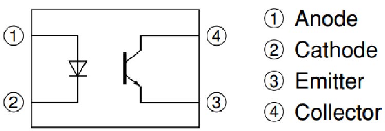
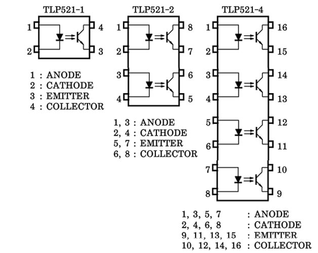
The TLP521 is an optocoupler that has a photo-transistor which is controlled based on light (photon). And on the opposite side, it has an IR (infrared) LED. When the IR LED is powered, the light from the LED is collected by the receiver of the transistor and it conducts. The arrangement and pinouts of the IR LED and the photo-transistor is shown below.
This IC is used to provide electrical isolation between two circuits, one part of the circuit is connected to the IR LED and the other to Photo-transistor. The digital signal given to the IR LED will be reflected on the transistor but there will be no electrical connection between the LED and the transistor. This comes in very handy when you are trying to isolate a noisy signal from your digital electronics, so if you are looking for an IC to provide optical isolation in your circuit design, then this IC might be the right choice for you.
Different Version of TLP521 Optocoupler
The TLP521 is a very versatile IC, and can be used for many different applications so there are many different versions available for this IC, there are three different version of this IC are available, the TLP521-1, TLP521-2, TLP521-3, they are 4-pin, 8-pin, and 16-pin devices those contain one, two, and four optocouplers in one single package respectfully, the pin configuration of these devices is shown below.
How to use TLP521 Optocoupler
Using the TLP521 IC is pretty much straight forward, we just have to connect the anode pin of the device to VCC and we have to connect the cathode to the ground. For this simulation, I am going to use a 1HZ square signal that will switch the device on and off with a frequency of 1Hz and I will also put an oscilloscope to the output of the device to see the difference in between the input and the output signal,
As the output device is a NPN transistor so we need to use a pullup resistor to pass current through collector to emitter. Now, when the logic input is low, the IR LED will not conduct and hence the transistor will also be in off state, but when the Logic input is made high, this high voltage should be a minimum of 1.25V (Diode Forward voltage) the IR LED conducts and so the photo-transistor is also turned on.
Another important parameter to consider while using an Optocoupler is the rise time (tr) and fall time (tf). The output will not get high as soon as the input logic is made low and vice versa. For TLP521, the rise time (TPDHL) and fall time (TPDLH) is 2uS and 3uS, respectively.
Applications
- Electrical Isolation circuits
- Microcontroller I/O switching circuits
- Signal isolation
- Noise coupling circuits
- Isolation digital from analog circuits
- Ac/DC Power control
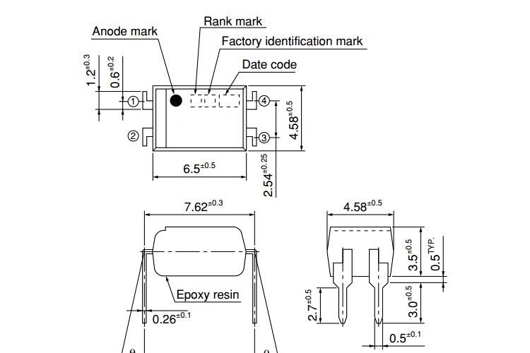
2D Model and Dimensions
If you are designing a PCB or Perf board with this component, then the following picture from the Datasheet will be useful to know its package type and dimensions.