NCP3066 Constant Current Regulator
NCP3066 or NCV3066 is a monolithic constant current regulator IC used for LED lighting applications. This IC can be found in marine, automotive lighting or any portable lighting applications. If you are looking for constant current DC-DC regulator upto 1.5A, then this IC might be the correct choice.
|
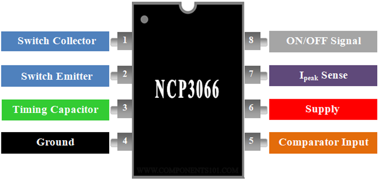
PIN NUMBER |
PIN NAME |
DESCRIPTION |
|
1 |
Switch Collector |
Internal Darlington switch collector |
|
2 |
Switch Emitter |
Internal Darlington switch emitter |
|
3 |
Timing Capacitor |
Timing Capacitor for Oscillator |
|
4 |
Ground |
Ground pin for all internal circuits |
|
5 |
Comparator Inverting Input |
Inverting input pin of internal comparator |
|
6 |
Vcc |
Input voltage for the IC |
|
7 |
Ipk Sense |
Peak current sensing pin |
|
8 |
ON/OFF |
ON/OFF pin. |
Features of NCP3066:
- Monolithic constant current Regulator IC.
- Input voltage (Vin): 3V to 40V.
- Integrated 1.5A switch.
- Low feedback voltage of 235mV.
- Higher operating frequency upto 150 kHz.
- Logic Level Shutdown Capability.
- Analog and PWM dimmable.
- Cycle−by−Cycle Current Limiting.
- Available in 8 pin DIP, SOIC and DFN packages.
Note: More technical details can be found at the complete NCP3066 datasheet linked at the bottom of this page
Alternatives for NCP3066:
LM3407, LM5008 and XL6009.
NCP3066 Equivalent:
NCP3065 and A6211.
How to use NCP3066 LED Driver IC:
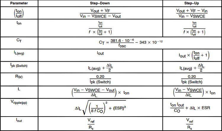
The NCP3066 is also called as NCV3066 and both shares the same datasheet. As mentioned above, this IC can be used for constant current LED Driver. Each mode has separate circuits that can be found on the datasheet. The IC is available as DIP, SOIC and DFN packages from the manufacturers. In addition to the various features, this IC has logic level shutdown capability that can be used to shutdown the regulator using logic signal. If the ON/OFF feature is not required, then the pin 8 of the IC can be connected to positive supply permanently. The design formula for all modes is given below.
The basic circuit for buck, boost current regulator using NCP3066 is given below. The inductor and the diode are the main components for both buck and boost topology. The LED’s may be connected series or parallel or both combinations but make sure that the voltage and current of the LED string does not go beyond the maximum rating of the IC.
Boost Converter design using NCP3066:
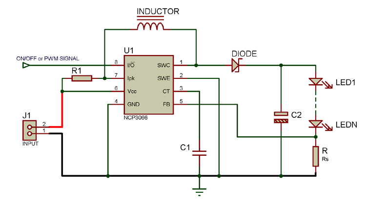
Buck Converter design using NCP3066:
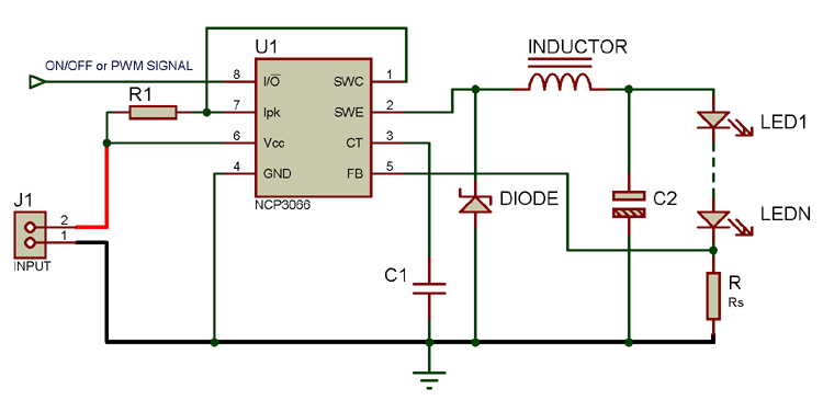
The basic schematic of buck and boost current regulator is shown above. The Rs is the current sense resistor for the LED string. The inverting input of the internal comparator monitors the voltage across the current sense resistor. If it goes above 235mV it turns OFF the internal Darlington transistor. The current sense resistor can be chosen by using the formula,
Rs = 0.235/Iload
During normal conditions, the current is monitored by internal comparator by using the voltage across the current sense resistor. If any abnormal condition occurs or the feedback voltage is lost during any fault or the voltage across the peak current sense resistor goes above 200mV with respect to Vcc, the peak current sense comparator turns OFF the internal Darlington transistor to protect the device. The value of the peak current sense resistor can be calculated by using the formula,
Rsc = 0.2/Ipeak of the Darlington switch. (Here, Rsc is R1 in the schematic)
Thus the current through the load is monitored on every switching cycle to control the load current to prevent overload. The maximum current rating of the Darlington switching transistor is 1.5A. So, make sure that the peak current of the application circuit must below the maximum current rating of the Darlington transistor.
The IC can be turned ON/OFF by applying logic signal on pin 8 of the IC. Pulling this pin below 0.8 V or leaving it open turns the IC into low power mode and shutdown the internal circuits. In this state the current consumption of the device is below 100uA. This gives an advantage for battery powered applications. Pulling this pin above 2.4V (upto 25V) turns ON the IC into normal working state. If the ON/OFF feature is not needed, this pin can be connected to the positive supply permanently. The brightness of the LED is controlled by giving 1 kHz positive pulse of 1% to 100% dutycycle.
Traditional buck/boost regulator requires a capacitor on output parallel to the load, to reduce the ripple on the output voltage. But, this IC NCP3066 focuses on the current control not the voltage across the load. By configuring the NCP3066 in continuous conduction mode with low peak-to-peak ripple, the output capacitor can be eliminated. This saves space and reduces part count for applications.
Applications:
- Automotive and marine lighting.
- Constant current power supplies.
- Battery powered portable lighting.
- High bright lighting applications.
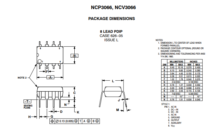
2D Model:
The physical dimensions of the IC in PDIP Package are given below.