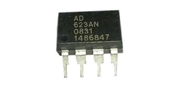
AD623 Instrumentation Amplifier IC
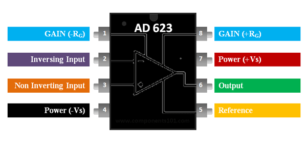
AD623 Pin Configuration
|
Pin Number |
Pin Name |
Description |
|
1 |
Gain (-Rg) |
Inverting Gain Terminal connected to resistor to set gain value |
|
2 |
Inverting Input (IN-) |
The Inverting input pin of the Op-Amp |
|
3 |
Non- Inverting Input (IN-) |
The Non - Inverting Input Pin of Amplifier |
|
4 |
Power (-Vs) |
Negative supply terminal |
|
5 |
Reference |
Output reference input. Normally connected to common |
|
6 |
Output |
Amplifier output pin |
|
7 |
Power (+Vs) |
Positive supply terminal |
|
8 |
Gain (+Rg) |
Non - Inverting Gain Terminal connected to resistor to set gain value |
AD623 Instrumentation Audio Amplifier Features and Specifications
- Rail to Rail Instrumentation Amplifier
- Can operate and Single and Dual supply voltage
- Operating current: 550uA (max)
- Gain Range: 1 to 1000
- Bandwidth: 800KHz
- Set gain with only one resistor
- Available in 8-Pin PDIP,SOIC and VSSOP packages
Note: Complete technical details can be found in the AD623 Datasheet linked at the bottom of this page.
AD623 Equivalents
Alternatives Amplifiers
LM4871, AD620, IC6283, JRC4558
Where to use the AD623 Instrumentation Amplifier?
The AD623 is an Instrumentation Amplifier with Rail to Rail feature. It also operates at a very low current of 550nA making it suitable for battery operated applications.
Instrumentation amplifier: Instrumentation amplifier is a type of differential amplifier that has buffer amplifiers connected to their input pins. This eliminates the need for impedance matching, thus making it practically suitable for measurement and test equipments.
Rail to Rail Op-Amp: The output pin of a normal op-amp will not be able to provide voltage that is equal to the supply voltage. This is because of the output stage transistors which prevent the amplifier from reaching the maximum positive voltage or minimum negative voltage. Rail to Rail Op-Amp overcomes this problem and hence the output pin can reach either positive rail voltage or negative rail voltage.
How to use AD623 IC
The AD623 only requires a resistor to sets its gain value and hence can be easily set up. A very basic commonly used circuit for AD623 is shown below.
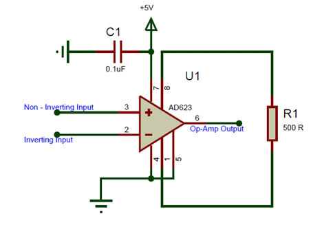
The IC is powered using the pin 7 and pin 4, here I have used a singly supply of +5V hence the pin 4 is grounded. If a dual supply voltage is used the pin 4 will be provided with negative voltage. The non - inverting pin (pin 2) and the inverting pin (pin 3) is connected the signal which has to be amplified or compared base on the application of the Op-Amp. The Reference pin (pin 5) is normally grounded along with pin 4, the reference pin is used to direct the output towards a voltage when the difference voltage between the inverting and the non-inverting pin is 0V.
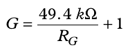
The Gain of an Op-Amp can be set by simply connecting the right value of resistor across the pin +Rg (pin 8) and the pin –Rg (pin 1). Here I have connected a resistor of value 500Ω which will set the Op-Amp at a gain value of 100. The formulae to calculate the value of gain from R is given below
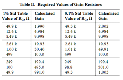
Alternatively you can also use the chart below which has the value of resistor and standard gain values listed.
Applications
- Power sensitive applications
- Calibration and test equipments
- Low Power Medical instrumentation
- Difference Amplifiers
- Data Acquisition devices
- Control system process
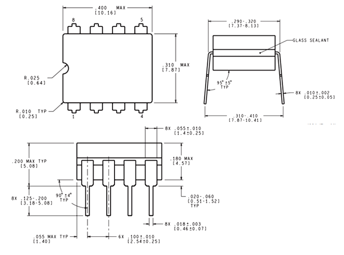
2D-Model and Dimensions