INA333 Instrumentation Amplifier
The INA333 device is a low-power, precision instrumentation amplifier offering excellent accuracy. The versatile 3-operational amplifier design, small size, and low power make it ideal for a wide range of portable applications.
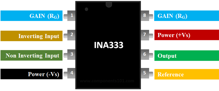
Pin Description of INA333:
|
Pin Number |
Pin Name |
Description |
|
1 |
Gain (Rg) |
Inverting Gain Terminal connected to a resistor to set gain value |
|
2 |
Inverting Input (IN-) |
The Inverting input pin of the Op-Amp |
|
3 |
Non- Inverting Input (IN-) |
The Non - Inverting Input Pin of Amplifier |
|
4 |
Power (-Vs) |
Negative supply terminal |
|
5 |
Reference |
Output reference input. Normally connected to common |
|
6 |
Output |
Amplifier output pin |
|
7 |
Power (+Vs) |
Positive supply terminal |
|
8 |
Gain (Rg) |
Non - Inverting Gain Terminal connected to a resistor to set gain value |
LM623 features and specifications:
-
Rail to Rail Instrumentation Amplifier
-
Number of Channels: 1 Channel
-
Operating Supply Voltage:5.5 V
-
SR - Slew Rate: 0.16 V/us
-
CMRR - Common Mode Rejection Ratio:100 dB
-
Ib - Input Bias Current:1.4nA
-
Vos - Input Offset Voltage:10uV
-
Operating Supply Current: 198uA
-
Bandwidth:150 kHz
-
Gain V/V:1000 V/V
- Available in 8-Pin PDIP, SOIC, and VSSOP packages
Note: Complete Technical Details can be found at the INA333 datasheet give at the end of this page.
Equivalent for INA333: AD623
Alternatives Instrumentaion Amplifiers: LM4871, AD620, IC6283, JRC4558
Where to use the INA333 Instrumentation Amplifier?
The INA333 is an Instrumentation Amplifier with Rail to Rail feature. It also operates at a very low current making it suitable for battery-operated applications. An instrumentation amplifier is a type of differential amplifier that has buffer amplifiers connected to their input pins. This eliminates the need for impedance matching, thus making it practically suitable for measurement and test equipment.
How to use INA333:
The INA333 only requires a resistor to sets its gain value and hence can be easily set up. A very basic commonly used circuit for INA333 is shown below.
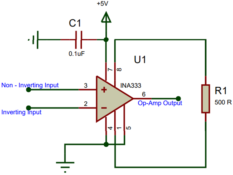
The IC is powered using pin 7 and pin 4 is connected to ground. Here I have used a single supply of +5V. The non - inverting pin (pin 2) and the inverting pin (pin 3) are connected to the signal which has to be amplified or compared base on the application of the Op-Amp. The Reference pin (pin 5) is normally grounded along with pin 4, the reference pin is used to direct the output towards a voltage when the difference voltage between the inverting and the non-inverting pin is 0V.
The Gain of an Op-Amp can be set by simply connecting the right value of the resistor across the pin +Rg (pin 8) and the pin –Rg (pin 1). Here I have connected a resistor of value 500Ω which will set the Op-Amp at a gain value of 100. The formulae to calculate the value of gain from R is given below.
G = (49.4 kΏ / RG) + 1
Applications of INA333:
- Bridge Amplifiers
- ECG Amplifiers
- Pressure Sensors
- Medical Instrumentation
- Portable Instrumentation
- Weigh Scales
- Thermocouple Amplifiers
- RTD Sensor Amplifiers
- Data Acquisition
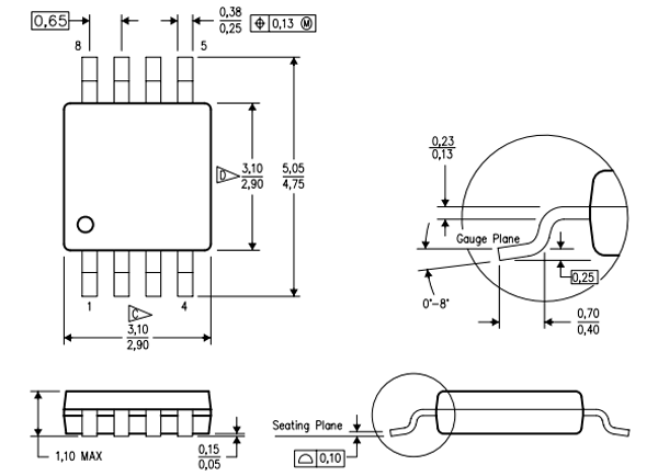
2D-Model INA333:
2-D dimensions for INA333 8-pin PDSO package is given below