

Optimized with highly sensitive cap touch sensors, extensive peripheral circuits and 125℃ operation
What is Optocoupler and How it works?
If you’ve ever taken apart any phone charger or a switching power supply, you’ll find some tiny black IC packages with an unusual number of pins, mostly four or six, both in SMD and through-hole variants. What is more unusual is that these parts are generally found over isolation slots and gaps, which makes their purpose more cryptic.
These components are called optocouplers or optoisolators or simply optos, and they perform the crucial function of passing signals between isolated sections of circuitry. They use light to pass signals between circuits.
What is Optocoupler and How It Works
As we have already learnt about transistors, an ideal transistor will not allow any current to pass through it if the base pin is not triggered. But, if you carefully manage to decap a regular discrete transistor and apply a voltage across the collector and emitter leads, you’ll notice that a tiny current still flows! This is because of the light that’s falling on the base of the exposed transistor die.
This means that the photons of light are actually able to knock the holes and electrons around in a doped semiconductor material. This leads to some very interesting possibilities, the first of which is the phototransistor, basically a two terminal transistor without a base lead. They look very similar to diodes and come in clear packages. Here, light acts as the base current. Photodiodes work in a very similar manner; they change their ‘resistance’ depending on the amount of light that falls on them.
Photodiodes and transistors are used in things like proximity sensors, which detect small changes in voltage or current across these devices depending on the amount of light that falls on them.
If we can put an LED and a phototransistor in a closed tube, the light coming from the LED (assuming it is properly driven, of course) will light up the ‘base’ of the phototransistor and render it conductive. This leaves us with a device that can control a switching element without any physical contact! Such a device already exists, and as you guessed, it is the optocoupler!
Optocoupler Inputs and Outputs
Optocouplers come in many different shapes, sizes and speeds (something which will be discussed later), but most of them have the same basic features – a diode input and a switching element output.
The diode is much like any other LED, except for the fact that you cannot see the light (firstly because it is in a sealed plastic package and secondly because it’s mostly infrared). It demands to be driven with the same currents and voltages that regular LEDs ask for, namely a few volts and a few tens of milliamps.
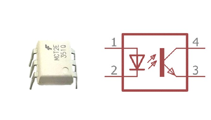
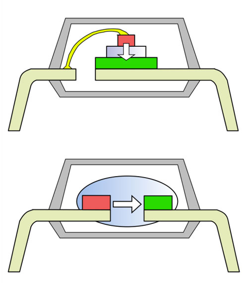
The below animation would help you understand the working. The Optocoupler used here is the MCT2E phototransistor IC. As you can see the logic input given to the LED controls the output of the transistor. In this IC the output side consists of a transistor, but it does have to be so in every case.
The output side of a photo transistor is a little more interesting because usually it consists of a NPN type transistor as shown above, but sometimes it can also be an SCR or a TRIAC, and sometimes even a full logic compatible output!
One big thing to remember is that since the base is basically driven by light, the ‘base current’ is very, very low – you can’t expect full saturation from these types of transistors, and since the base current is so small, the rise and fall times are often pathetically slow, as I learnt the hard way. Of course, logic output (and matching speeds) optos are available, but require a separate power supply for the output side.
The nice thing about the opto output is that since it is completely galvanically isolated from the input side, it can float at any voltage – or in other words, it acts like a floating ‘switch’, though not a very good one.
For example you can place the transistor output on the low side and add a pullup to the collector, so when the diode is lit up the transistor conducts and pulls the collector low. You could also place the transistor on the high side with a resistor between emitter and output ground, so when the input goes high the output at the emitter is high too.
But beware, most common optos have a high saturation voltage because of the limited base drive, sometimes in the order of 1 Volt!
Because of their slow speed, regular optos are used as part of power supply feedback loops, with the added bonus of complete isolation.
As you may have guessed, optos cannot do something that transformers can – supply power. While a transformer can power isolated circuitry, with current technology we cannot efficiently transfer power though light.
But optos do something transformers cannot – pass signals between circuits very efficiently and very quickly, without the need for separate drivers. We can hook the input of an opto directly to a microcontroller pin, but we wouldn’t be able to do the same for a signal transformer!
Practical Optocoupler Advice
For all ‘slow’ purposes, i.e. signals in the order of a few kilohertz, I recommend using the PC817, a very common single opto which comes in a DIP4 or SMD package. Supply the input with at least 5mA.
For higher speeds, I recommend the TLP117, which has an inverted logic output but requires a 5V supply on the output side. I’ve gotten 10 microsecond pulses out of this one, that should be able to tell you something about its speed!
As insignificant as it may seem to read the whole datasheet, you’d be better off actually doing it.
Other Optically Coupled Devices
Building upon the same technology we find a range of useful devices – opto SCRs and opto TRIACs. Opto TRIACs are more commonly known as solid state relays or SSLs. They basically act like regular relays but use light to trigger the hot side TRIAC, which consumes a lot less current than a relay coil.
One disadvantage is that semiconductor devices tend to fail shorted, while electromechanical relays fail open. This is something to keep in mind in critical applications.
Opto SCRs on the other hand are usually used to trigger larger power SCRs from an isolated signal.


