Arduino UNO Q bridges high-performance computing with real-time control.
Current Sense Resistors - Types, Specifications, Selection, and Application Guide
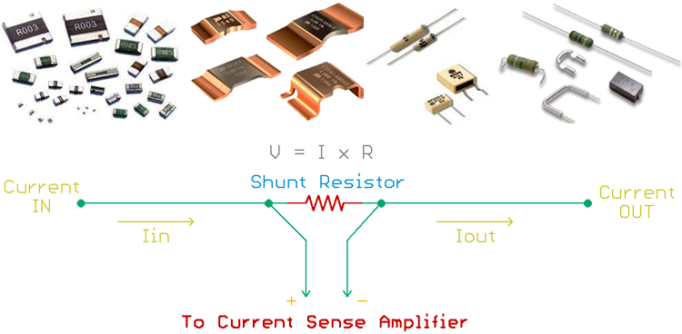
Sensing the current flow is an important thing in many power and general electronics applications. Often, current sensing is required to monitor and control an application, for example, a battery charger circuit requires current sensing technique to properly charge the battery and to determine the charge current from the driver, controller perspective. Depending on the type of application, there are many types of current sensors with different current sensing techniques that are used to measure or detect current flow. The most commonly used and cost-effective solutions for current sensing is the shunt current sensor method. The shunt current sensor, also known as sense resistor is similar to a basic resistor but with very low resistance value. In this article, we will more about this current sensor, how they work, its types, and how you can use one in your designs.
What is Current Sense Resistor?
Current Sense Resistors are similar to normal resistors but with very low resistance rating and high-power rating. These shunt resistors of known resistor value (R) are placed in a current conducting path so that the entire current (I) which is to be measured flows through the resistors. Now by measuring the voltage drop (V) across the resistor and by using simple Ohms Law (I=V/R), we can calculate the amount of current that flows through the circuit. Let’s look at that in detail.
In electronics, shunt means providing a different path to the circuit. Shunt resistors do the same thing and create a very low resistance path for the current to pass from one circuit portion to another circuit portion. At this path, whenever a current passes through the low resistance region, irrespective of the amount of current flow, one can measure how much current is flowing through the circuit.
As this is resistance and due to the flow of current, a voltage drop occurs across the shunt resistor. This voltage drop is directly proportional to the flow of current. If the current flow increases, the voltage drop will also increase. This relationship follows Ohm's law.
That is,
V = I x R
Where V is the Voltage drop that appears across the shunt resistor, I is the rate of current flow, and the R is the shunt resistor value in Ohms. Therefore, if the resistance is static, for example, 1 ohm for all the cases, the V is dependent on the I.
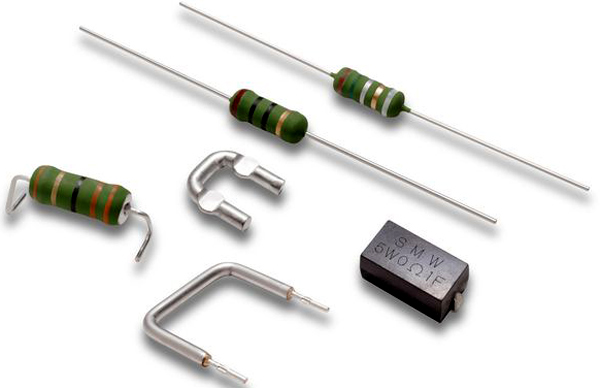
But the selection of this shunt resistance is a crucial thing for accurate reading of the current flow without hampering the circuit's overall performance. But before selecting the right shunt resistor, it is important to find out the parameters of shunt resistors. For different applications, different shunt resistors may be required where the parameters are changed in each shunt resistor depending on the requirement of the application.
Shunt Resistor Parameters
Shunt resistors are the special type of resistors. It is different from the traditionally used resistors in electronic circuits. The generic resistors are used for the very low current of operations and are generally used in standard ambient temperatures such as 0-85 Celsius. But, shunt resistors have a very wide range of temperature coefficients due to the huge current flow through it.
The major difference between a standard resistor and shunt resistor is the temperature coefficient of thermal EMF. In normal resistors, the thermal EMF is ignored but in shunt resistors, depending on the temperature, two different conductive materials produce a variable voltage. Thus, the selection of the element material shunt resistor is an important thing. Most of the time, manganin (-3.0 uV / oC Thermal EMF with excellent Temperature coefficient range) is used to make the exposed blade shunt resistor. Thus, choosing the proper shunt resistor is not limited to the resistor value and tolerance only.
Resistance and Power Rating of Shunt Resistor
The value of resistors is an important parameter for a shunt resistor. Because the value will determine how much voltage will drop during the flow of current.
The value can be determined from the current sense amplifier perspective. Depending on the maximum current flow and the maximum input voltage of the current sense amplifier, the value of the shunt resistor can be chosen. However, a larger value affects the power rating of the shunt resistor and increases the heat dissipation.

The above current sense resistor circuit shows how a shunt resistor is placed in a current carrying path and how the voltage drop across the resistor can be calculated by using a Current Sense Amplifier. You can know more about how current sense amplifiers work for following the linked article.
The power dissipation of the shunt resistor can be determined using the below formula-
Power dissipation = V x I
Where V is the voltage, I is the current. Since the drop voltage across a shunt resistor can be determined using Ohm's law. The power dissipation of a shunt resistor can be determined using-
Power dissipation = I2R
Thus, a shunt resistor with a smaller value will produce less heat and overrule the use of additional heat sink.
Shunt resistor values typically in mili-ohms rating are typically suitable and produce less power dissipation in high current flow. The wattage of the resistor will be lower and the size will be very smaller, contributing to a smaller PCB area.
However, Shunt resistor power dissipation can also be identified using the PCR value of a resistor. PCR stands for Power Coefficient of Resistance (ppm per Watt) and characterizes the different values of power dissipation of different value resistors.
Tolerance of Shunt Resistor
Since nothing is ideal in electronics, shunt resistors are not an exception. Thus, tolerance of the shunt resistors is an important parameter for the sensing accuracy of the Shunt resistor. Normal generic resistors have tolerances of 10%, 5%, or even 1%. Therefore, A resistor with 10 Ohms rating with a 10% tolerance will have the value from 9 Ohms to the 11 Ohms. The value will get changed due to the ambient temperature and other additional dependencies during normal operations.
However in most applications, resistor tolerances will not matter a lot but for an application where the application output is highly dependent on the sensed value, tolerance becomes a crucial parameter to consider.
Shunt resistor tolerance ranges from 1% to 0.1%, however, how much accuracy is required is entirely dependent on the application requirement and the resistor needs to choose based on this parameter.
Temperature Coefficient of Shunt Resistor
TCR or Temperature Coefficient of the resistor (ppm/°C) is the parameter that determines how much resistance will change by the changes in the temperature of the resistor. It is an essential parameter in the shunt resistor application where it is not significant for general-purpose resistors. It is not difficult to find out thousands of ppm per degree Celsius rating for an ordinary 1% resistor, but it needs to be very low for the shunt resistor because due to the high current flow, the power dissipation of a shunt resistor could be larger and that will increase the resistor temperature. Due to the increased resistor temperature, the resistor value could be changed and possibly provide reading with errors.
The TCR value is dependent on the materials that are used as resistor elements, depending on the tolerance and power rating as well as the physical size of the resistor. There are multiple shunt resistors available that use very low TCR value due to metal-foil elements used as the resistor materials.
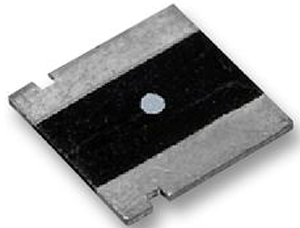
The above image is a metal foil-based resistor from VISHAY FOIL RESISTORS with the part number of Y14880R00100D9R.
Placing Shunt Resistor in your Design
The placement of Shunt resistors can be two types, high side placement and low side placement. In high side placement, the shunt resistor is placed across the high side of the load (positive rail).
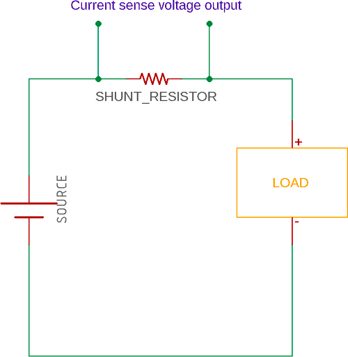
This shunt placement is widely used and often it requires a differential amplifier to sense the actual current flowing through the resistors. In low side placement, the shunt resistor is placed across the low side (Ground or negative rail) of the load.
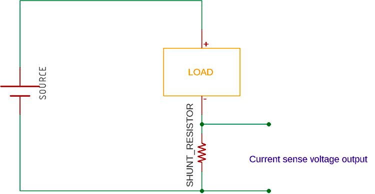
However, this placement offset the load ground and often makes it difficult to determine the short circuit condition of the load.
Both shunt resistor placements and as always, it will induce a voltage drop across the shunt resistor that can be used to sense the current flowing through the load, as well as through the resistor.
How to Choose Shunt Resistor for an Application
Since a shunt resistor poses different types of parameters that are suitable for a specific type of application (depending on the current, voltage rating, application requirement), it is important to select a shunt resistor based on the type of application it is required for. If you are looking for quick testing, you will also find a pre-built shunt resistor module like the INA219 Shunt Resistor Module.
Therefore, the first step to select a shunt resistor is important to know the type of application. Especially for a current amplifier or for an ADC, how much input voltage it supports as the maximum input voltage, is an important factor to determine the value of the shunt resistor. Because the output voltage ‘V’ is dependent on the flow of current ‘I’ through a shunt resistor with a value ‘R’, comprised of V = I x R. Therefore, depending on the flow of current and the maximum input voltage of the sensed circuitry, the shunt resistor value can be chosen. Try best to choose a resistor value in milliohms rating.
The second step is to know the power rating of the Shunt resistor. As in the first step, the value of the shunt resistor is already selected and the maximum current flow will be known, it is important to know how much power it will dissipate using the formula P = I2R. Therefore, if the value is smaller, the power dissipation will be less. Depending on the power dissipation, for example, a resistor with 50 mili-ohms ratings will pass a maximum of 2A current, the power will be dissipated 22 x 0.05 Ohms = 0.2 Watt. It is safer to use more than the rated power rating for the shunt resistor. So instead of a 0.25-Watt shunt resistor, one can use at least 0.375-Watt resistor to be on the safe side.
The third step is to know the tolerance and package required for the shunt resistor. Less than the 1% tolerance shunt resistor is a good choice. But if application demands more for extra accuracy, 0.5% to 0.1% tolerance shunt resistors can also be used. After choosing the value, power rating, and tolerance, it is important to use a proper package that is easy to solder as well as smaller in sizes for smaller PCB areas. Try to select a resistor with a very low TCR value below 100 ppm/°C.
Current Sense Shunt Resistor Reference Design – Case Study
Here is a practical example of shunt resistor selection for an MPPT based solar charge controller circuit. The below circuit uses LT3652, an MPPT charge controller from Linear Technology (Analog devices). However, If we look carefully, the battery that will be charged through this circuit is the load.
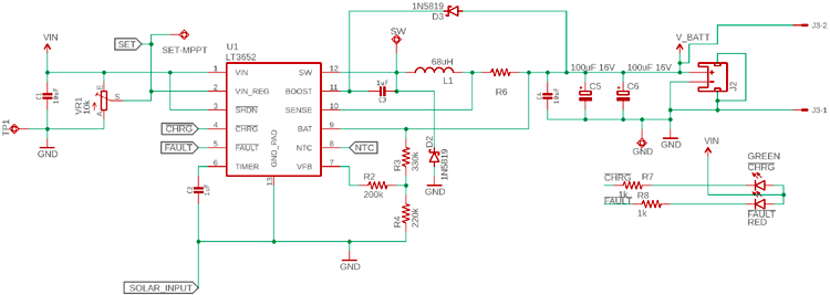
The load is connected using a shunt resistor R6. The R6 will determine the charge current, which means the voltage drop of this R6 will remain constant in every case as V = I x R. The R will be constant, the V will be constant, the driver will change the charge current.
To select the shunt resistor, the following things will be required-
- The constant voltage that will be used by the driver IC LT3652
- The maximum charge current that is required to be delivered to the battery through the resistor.
- Since it is a charge controller tolerance could be 1%.
As per the LT3652 datasheet, the sense pin will use 100 mV (0.1V) sense voltage that will be constant. Also, the maximum charge current LT3652 supports is 2A. Thus, the Shunt Resistor value needs to be R = V / I or Shunt resistor value will be 0.1V / 2A = 0.05 Ohms or 50 mili-ohms.
The power rating of this resistor needs to be P = I2R or P = 22 x 0.05 = 0.2 Watt. The close value of the shunt resistor will be 50 mili-ohms, 1% rated, 0.25 Watt. But instead of 0.25 Watt, 0.375 Watt is the safe resistor wattage that can be used.


