

Optimized with highly sensitive cap touch sensors, extensive peripheral circuits and 125℃ operation
Introduction to Schmitt Trigger
What is a Schmitt Trigger?
A Schmitt trigger is a comparator (not exclusively) circuit that makes use of positive feedback (small changes in the input lead to large changes in the output in the same phase) to implement hysteresis (a fancy word for delayed action) and is used to remove noise from an analog signal while converting it to a digital one. Understanding Schmitt triggers and how they work is what we are going to do in this article.
It was invented way back in 1937 by Otto H. Schmitt (whose legacy is somewhat understated) who called it a ‘thermionic trigger’.
Why Schmitt Triggers?
Comparators by nature are very fast, since they lack the compensating capacitor found in their op-amp cousins. Comparators are not limited by output slew rate and transition times are in the order of nanoseconds. Comparators also have especially sensitive inputs because of their very high gain – even tiny changes in the input can cause instant change of state on the output.
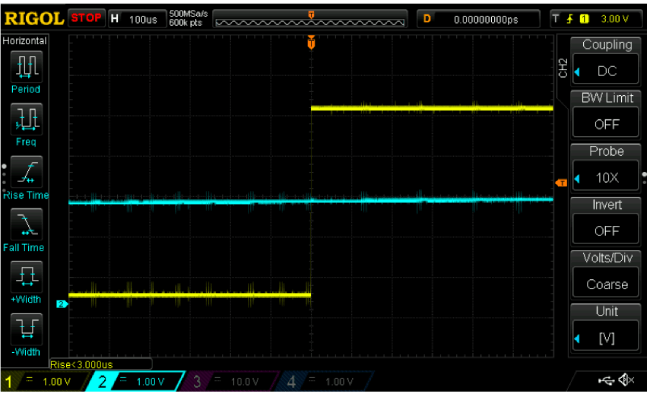
This problem gets worse when the differential input signals reach the dead zone, that is, the minimum input differential voltage required to maintain a stable output. Within this narrow range, the comparator has no idea what to do with its output – which leads to something called motorboating, which is the output oscillating. This problem also occurs with signals that have a slow transition time – the input signal spends enough time in the dead zone (with reference to the reference voltage, of course) to create multiple output transitions, as shown in the figure below.

If you notice carefully, the input signal varies with the output swing and there’s a lot of noise on the supply rail (as seen on the output through the pullup resistor), which is a result of poor decoupling!
If there was any logic connected to the output (which in most cases is true), it would detect the multiple transitions and cause havoc – flip flops would toggle multiple times, maybe causing something important to reset.
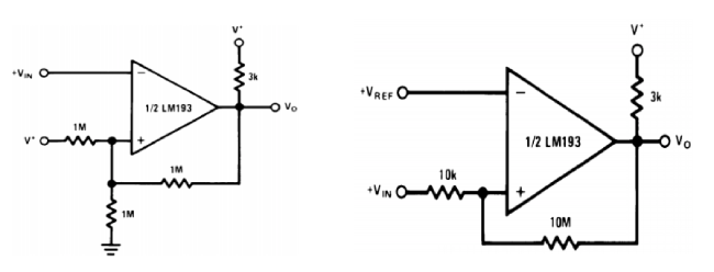
This is something that can be remedied using hysteresis – in this case with the addition of a single resistor between the inverting terminal (which in this case is the reference) and the output. The difference is marked, again from the figure.
Again, note the unstable reference voltage.
Types of Schmitt Triggers - Non-Inverting and Inverting Schmitt Triggers
Based on the configuration of the circuit and the polarity of the output relative to the input signal we can classify Schmitt triggers into two types - Non-Inverting and Inverting Schmitt Triggers.
Inverting Schmitt Trigger
An inverting Schmitt trigger provides a high output when the input is below the lower threshold and a low output when the input is above the upper threshold. The feedback resistor inverts the logic levels, creating a hysteresis loop that ensures clean transitions. Here is a simple simulation of an inverting Schmitt trigger.
INVERTING SCHMITT TRIGGER OSCILLATOR SIMULATION
And he is the hysteresis curve for the same.
INVERTING SCHMITT TRIGGER OSCILLATOR HYSTERESIS SIMULATION
Applications of Inverting Schmitt Triggers
- Waveform shaping to produce clean digital signals from noisy analog inputs.
- Pulse width modulation (PWM) circuits.
- Oscillator circuits.
Advantages of Inverting Schmitt Triggers
- Inverted output provides an alternative signal processing option.
- Useful in circuits where an inverted logic signal is required.
Non-Inverting Schmitt Trigger
A non-inverting Schmitt trigger provides a high output when the input is above the upper threshold and a low output when the input is below the lower threshold. This configuration uses a feedback resistor but does not invert the logic levels, maintaining the input signal's polarity. Here is a simulation show casing a non inverting Schmitt trigger.
NON INVERTING SCHMITT TRIGGER OSCILLATOR SIMULATION
And here is its hysteresis curve.
NON INVERTING SCHMITT TRIGGER OSCILLATOR HYSTERESIS SIMULATION
Applications of Non-Inverting Schmitt Triggers
- Signal conditioning to remove noise from analog signals.
- Generating square waves from a noisy sine wave input.
- Used in debouncing circuits for mechanical switches.
Advantages of Non-Inverting Schmitt Triggers
- Provides a clear distinction between high and low states, minimizing noise-induced errors.
- Simple design with easy-to-configure thresholds.
Characteristics of Schmitt Trigger
Here are the key characteristics of Schmitt triggers:
- Hysteresis: Schmitt triggers exhibit hysteresis, providing two distinct threshold voltages for switching the output state. The input must cross these thresholds to change the output, ensuring noise immunity.
- Upper Threshold Voltage (V_U): This is the input voltage level at which the output switches from low to high in a non-inverting Schmitt trigger or from high to low in an inverting Schmitt trigger. It determines when the output should change state based on the rising input voltage.
- Lower Threshold Voltage (V_L): This is the input voltage level at which the output switches from high to low in a non-inverting Schmitt trigger or from low to high in an inverting Schmitt trigger. It ensures the output only changes state when the input voltage falls below this level, providing stability.
- Bistable Nature: Schmitt triggers have two stable states, high and low. The output remains in one state until the input crosses a threshold voltage, causing a switch to the other state. This bistable behaviour is essential for applications requiring stable and distinct output states.
- Positive Feedback: Positive feedback ensures that small changes in the input lead to large changes in the output. This reinforcement of the output state prevents multiple transitions and helps achieve rapid switching, contributing to the stability and performance of the Schmitt trigger.
- Noise Immunity: The hysteresis in Schmitt triggers filters out noise from the input signal. This means that minor fluctuations in the input do not affect the output state, which is crucial in digital circuits, ensuring clean and debounced digital signals.
- Speed of Operation: Schmitt triggers can quickly switch between states, making them suitable for high-frequency applications. Their low propagation delay enhances their effectiveness in fast digital circuits and timing-sensitive applications.
- Symmetric or Asymmetric Thresholds: Schmitt triggers can have symmetric or asymmetric thresholds. In symmetric designs, V_U and V_L are equidistant from the reference voltage, while in asymmetric designs, V_U and V_L can be set at different distances. This flexibility allows the Schmitt trigger to be tailored to specific applications.
How Does a Schmitt Trigger Work?
A Schmitt trigger makes use of positive feedback – it takes a sample of the output and feeds it back into the input so as to ‘reinforce’, so to speak, the output – which is the exact opposite to negative feedback, which tries to nullify any changes to the output.
This reinforcing property is useful – it makes the comparator decide the state of the output it wants, and makes it stay there, even within what would normally be the dead zone.
Consider this simple circuit:
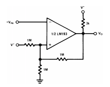
Assume the input voltage is lower than the reference voltage at the non-inverting pin and the output is therefore high.
V* is the reference input voltage which creates a fixed bias at the non-inverting input. Since the output is high through the pullup resistor, this creates a current path through the feedback resistor, slightly increasing the reference voltage.
When the input goes above the reference voltage, the output goes low. Normally this shouldn’t affect the reference voltage in any way, but since there’s a feedback resistor, the reference voltage drops slightly below the nominal value because the feedback and the lower reference resistor are now in parallel with respect to ground (since a low output shorts that terminal of the resistor to ground). Since the reference voltage is lowered, there is no chance of a small change in input causing multiple transitions – in other words, there is no longer a dead zone.
To cause the output to go high, the input must now cross the new lower threshold. Once crossed, the output goes high and the circuit is ‘reset’ to the initial configuration. The input has to cross the threshold just once resulting in a single clean transition. The circuit now has two effective thresholds or states – it is bistable.
This can be summarised in the form of a graph:
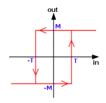
This can be understood in the usual sense – the x axis is the input and y axis is the output. Tracing a line from x to y, we find that once the lower threshold has been crossed, the hysteresis goes high and vice versa.
The operation of the non-inverting comparator is similar – the output again changes the configuration of a resistor network to change the threshold to prevent unwanted oscillations or noise.
Schmitt Trigger vs Comparator
A comparator provides a binary output based on the comparison of two input voltages but lacks hysteresis. In contrast, a Schmitt trigger includes hysteresis, providing better noise immunity and stable output transitions. While a comparator can produce multiple transitions if the input is noisy or slow, a Schmitt trigger provides a single clean transition.
Schmitt Trigger vs Buffers
Buffers are used to drive higher loads without changing the logic level, whereas Schmitt triggers are used to clean up noisy signals. While some buffers may include Schmitt trigger inputs, not all do. Buffers generally do not have hysteresis, which means they cannot filter out noise as effectively as Schmitt triggers.
CMOS Schmitt Trigger
CMOS Schmitt triggers are integrated circuits that use complementary metal-oxide-semiconductor technology. They offer low power consumption and high noise immunity, making them suitable for battery-powered and portable applications. CMOS technology ensures that the Schmitt triggers can operate at very low voltages and consume minimal power.
Advantages and Disadvantages of Schmitt Triggers
Here are some of the advantages and disadvantages of Schmitt triggers.
Advantages
- Noise Immunity: Effective in removing noise from input signals, ensuring stable and clean output transitions.
- Stable Output: Provides stable transitions, avoiding multiple output states and preventing false triggering.
- Versatility: Can be used in various applications like oscillators and debouncing circuits, making them highly adaptable in electronic designs.
Disadvantages
- Design Complexity: Requires careful design to set appropriate thresholds, which can be challenging in complex circuits.
- Power Consumption: May consume more power than simple comparators due to feedback resistors and additional components involved in creating hysteresis.
Applications of Schmitt Triggers
Schmitt triggers find a wide range of uses mostly as logic inputs. Again, it’s not a nice thing to have a single logic threshold, in case of noisy or slow signals multiple output transitions may result. Reading the datasheet of any logic chip, you’ll find that two thresholds are specified – one for a rising edge and one for a falling edge – this is evidence of Schmitt input action.
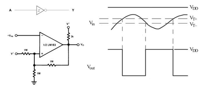
Sometimes logic gates are drawn with a little ‘lightning’ symbol inside them, this is a stylized hysteresis curve indicating that the device has Schmitt trigger inputs.
1.Simple Oscillators
Having two thresholds gives Schmitt triggers the 555 like ability to act like predictable oscillators.
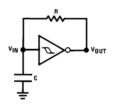
Assume that the capacitor is initially uncharged.
The gate detects this as an input low and sets the output high, since it’s an inverting gate. The capacitor begins charging thought the resistor R. Once the upper threshold is reached, the gate flips to output low, discharging the capacitor to the low threshold, providing a predictable frequency output.
The expression for frequency can be derived with a little mathematical juggling:
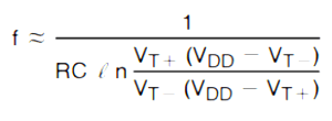
Where R and C are the resistance and capacitance, VT + is the upper threshold, VT – is the lower threshold and VDD is the supply voltage. Note the ‘approximately equal to’ symbol. Here is a simple simulation for the above circuit.
SIMPLE SCHMITT TRIGGER OSCILLATOR SIMULATION
2. Switch Debouncing
Mechanical switches as logic inputs are not exactly the best idea. The switch contacts tend to be somewhat springy, causing a lot of unwanted jitter, which again can cause multiple transitions and glitches further down the line.
Using a Schmitt trigger with a simple RC circuit can help mitigate these problems.
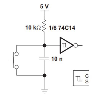
When the switch is pressed, it discharges the capacitor and causes the output to go high for a moment till the capacitor charges up again, creating a clean pulse on the output.
Where Can I Find Schmitt Triggers?
Schmitt triggers are better known as buffers or inverters in the logic world – but beware, not all gates are Schmitt triggers. Like all logic, they’re available in DIP or SMD form, with multiple gates on a single package. A good example is the 74HC04, which is a hex inverter with Schmitt trigger inputs.
Of course, other logic gates like the 4081 quad AND gate have Schmitt inputs too.
Conclusion
Schmitt triggers are useful when noisy signals are involved – they clean up the noise and prevent unwanted multiple transitions and oscillation.


