

Optimized with highly sensitive cap touch sensors, extensive peripheral circuits and 125℃ operation
Metal Oxide Varistor (MOV) – Working, Application, Design Tips and Selection Guide
A Metal Oxide Varistor or MOV is the blue or orange-colored circular component that you can commonly spot on the AC Input side of any Power Supply Circuit. The Metal Oxide Varistor can be considered as another type of variable resistor that can vary its resistance based on the applied voltage across it. When a high current passes through a MOV, its resistance value decreases and acts as a short circuit. Hence MOVs are normally used in parallel with a fuse, to protect circuits from high voltage spikes. In this article, we will learn more about MOV Working and how to use it in your designs to protect your circuits from voltage spikes. We will also learn about the electrical properties of MOV and how to select a MOV according to your design requirements, so let get started.
What is a MOV (Metal Oxide Varistor)?
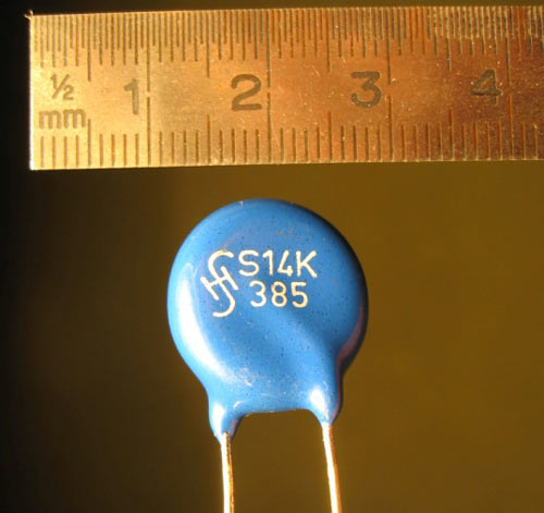
MOV is simply a variable resistor, but unlike potentiometers, MOVs can change its resistance based on the applied voltage. If the voltage across it increases the resistance decreases and vice versa. This property is useful in protecting the circuits from high voltage spikes; hence they are mostly used as surge protectors in an electronic network. A simple MOV is shown in the below picture
How does MOV work?
During normal operating conditions the resistance of the MOV will be high and they will draw very little current but, when there is a surge in the network, the voltage will rise above the knee or clamping voltage and they draw more current, this dissipates the surge and protects the equipment. The MOVs can only be used for short surge protection, they can’t handle sustained surges. If the MOVs are exposed to repeated surges their properties might slightly get degraded. Whenever they experience a surge the clamping voltage drops a little lower, after some time this can even lead to their destruction. To avoid these kinds of risks MOVs are mostly connected in series with a thermal switch/fuse that could activate if high current is drawn. Let’s discuss more on how MOV working in a circuit.
How to use a MOV in your circuit?
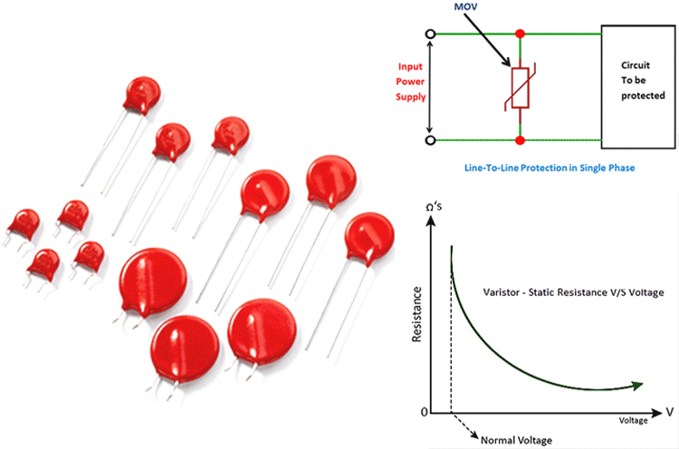
MOV a.k.a varistors is commonly used along with fuse in parallel to the circuit that is to be protected. The below image shows how to use MOV in the electronics circuit.
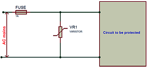
When the voltage is within the rated limits the resistance of the MOV will be very high and hence all the current flows through the circuit and no current flows through the MOV. But when a voltage spike occurs in the main voltage, it appears directly across the MOV since it is placed in parallel to AC mains. This high voltage will decrease the resistance value of the MOV to a very low value making it appear like a short.
This forces a large current to flow through the MOV which would blow the fuse and disconnect the circuit from the mains voltage. During voltage spikes the faulted high voltage will return to normal values very soon, in those cases, the duration of the current flow will not be high enough to blow the fuse and the circuit returns to normal operation when the voltage becomes normal. But, every time a spike is detected the MOV disconnects the circuit momentarily by shorting itself and damaging itself with high current each time. So if you find a MOV damaged in any power circuit it is possibly because the circuit went through many voltage spikes.
MOV Construction
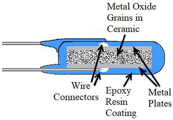
Metal Oxide Varistor is a voltage-dependent resistor that is made with ceramic powders of metal oxides like Zinc oxide and some of the other metal oxides like oxides of cobalt, manganese, bismuth, etc. A MOV consist of approximately 90% of Zinc oxide and a small amount of other metal oxides. The ceramic powders of the metal oxides are kept intact between two metal plates called the electrodes.
The grains of metal oxides create a diode junction between each immediate neighbor. So, an MOV is a large number of diodes connected in series. When you apply a small voltage to the electrodes a reverse leakage current appears across the junctions. Initially, the generated current will be small but when a large voltage is applied to the MOV the diode border junctions break down due to electron tunneling and avalanche breakdown. The internal structure of a MOV is shown in the below picture.
The MOV varistor starts conducting when a specific voltage is applied across the connecting leads and stops conducting when the voltage falls below the threshold voltage. MOVs are available in various formats like disk format, axially leaded devices, blocks and screw terminals and radial leaded devices. The MOVs should always be connected in parallel for increased energy handling capability and if you want to get higher voltage rating you should connect it in series.
Electrical Characteristics of MOV
Let’s look into the different electrical characteristics of MOV to better understand the MOV properties.
Static Resistance
The Static Resistance curve of a MOV is plotted with the resistance value of MOV in X-axis and Voltage value in the Y-Axis.
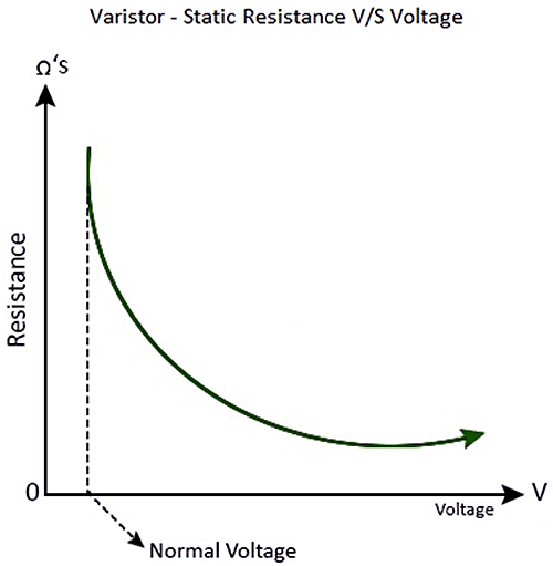
The above curve is the voltage and the resistance curve of a MOV, at the normal voltage the resistance is at its peak, but as the voltage increases the resistance of the varistor decreases. This curve can be used to understand how much resistance will be across your MOV at different voltage levels.
V-I Characteristics
According to ohms law, the V-I characteristic curve of a linear resistor is always a straight line, but we can’t expect the same in terms of a variable resistor. As you can see in the below image, if there is even a small change in the voltage there is a significant change in current also.
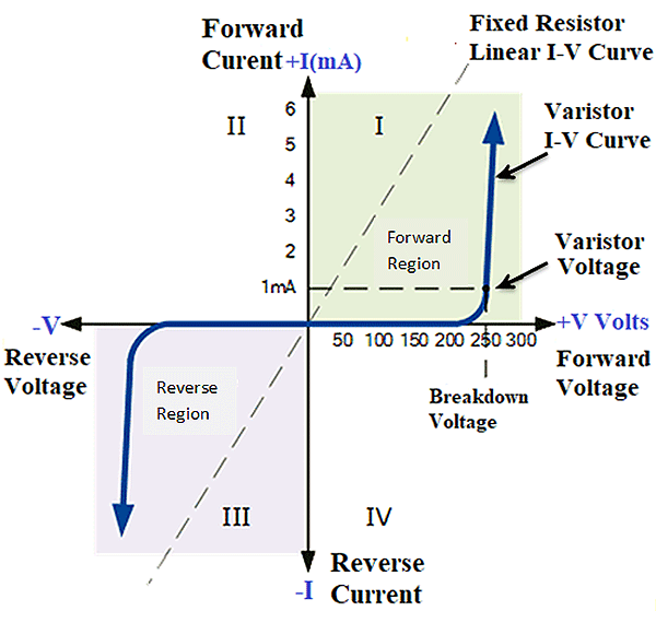
The MOV can operate in both the directions, hence it has symmetrical bi-directional characteristics. The curve will look similar to the characteristic curve of two Zener diodes connected back-to-back. When the MOV is not conducting it has a high resistance up to certain voltage say 0-200Volts the Curve has a linear relationship, where the current flowing through the varistor is almost zero. When we increase the applied voltage in the range of 200-250V, the resistance decreases and the varistor starts conducting and a few micro-amperes of current starts flowing, which doesn’t make much difference in the curve.
Once the rising voltage hits the rated or clamping voltage (250V) the varistor becomes highly conductive, about 1mA of current starts flowing through the varistor. When the transient voltage across the varistor is equal to or higher than the clamping voltage the resistance of the varistor becomes small which turns it into a conductor due to the avalanche effect of the semiconductor material.
Capacitance of MOV
As we have already known that the MOV is constructed with two electrodes it acts as a dielectric medium and posses the effects of the capacitor which could affect the working of the system if it isn’t taken under consideration. Every semiconductor varistors will have capacitance value depending on the area which also inversely depends on its thickness.
The Capacitance value is not a big deal when it comes to a DC circuit since the capacitance will remain almost constant until the voltage of the device reaches the clamping voltage. There will not be any capacitance effect when the voltage reaches the clamping voltage as the varistor starts its normal functioning.
When it comes to AC circuits the capacitance of the MOV might affect the overall body resistance of the MOV which causes leakage current. Since the varistor is connected parallel with the device to be protected the varistor leakage resistance drops rapidly when the frequency increases. The reactance value of the MOV can be calculated using the formula
Xc=1/2πfC
Where Xc is the capacitive reactance and f is the frequency of the AC supply. If the frequency increases the leakage current will also increase as shown in the non-conducting leakage region of the V-I characteristics curve discussed above.
Choosing the right MOV for Protection
You should know about the various numbers of parameters of a MOV to choose the right device for your pieces of equipment. The Specification of a MOV depends on the following
- Maximum Working Voltage: It is the steady-state DC voltage to which the typical leakage current will be less than the specified value.
- Clamping voltage: It is the voltage at which the MOV starts to conduct and dissipate the surge current.
- Surge Current: It is the maximum peak current that can be given to the device without causing any device damage; it is mostly expressed in ‘current for a given time’. Although the device can handle the surge current the manufacturers recommend replacing the device if there is an occurrence of surge current.
- Surge Shift: Whenever the device experiences a surge the rated clamping voltage decreases, the variation in the voltage after the surge is called the surge shift.
- Energy Absorption: The maximum amount of energy that the MOV can dissipate for a specified peak pulse time of a specific waveform during a surge. This value can be determined by running all the devices within a specific controlled circuit with specific values. The Energy is usually expressed in standard transient x/y where x is the transient rise and y is the time to reach its half peak value.
- Response Time: It is the time at which the varistor starts conducting after the occurrence of the surge, in many instances, there isn’t an exact response time. The typical response time is always fixed as 100nS.
- Maximum AC Voltage: It is the maximum RMS line voltage that can be given to the varistor constantly, the maximum RMS value should be chosen to be slightly above the actual RMS line voltage. The peak voltage of the sine wave should not overlap with the minimum varistor, if it does, it might reduce the lifetime of the components. The manufacturers will specify the maximum AC Voltage that we can provide to the device in the product description itself.
- Leakage Current: It is the amount of current drawn by the varistor when it is operating below the clamping voltage that is when there is no surge in the network. Usually, the leakage current will be specified at a given operating voltage across the device.
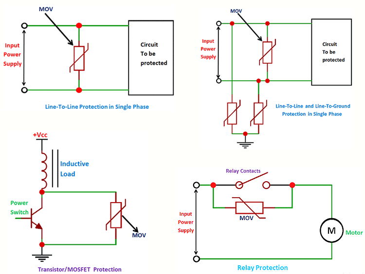
Applications of MOV
The MOVs can be used for protecting various types of equipment from different types of faults. They can be used for single-phase line to line protection and single-phase line to line & line to ground protection in AC/DC electrical circuits. They can be used for semiconductor switching protection in transistor, MOSFETs or Thyristor and Contact arcing protection in motor-operated devices.
When it comes to application, the MOVs can be used in circuits where ever there is a risk of a surge or voltage spikes. The MOVs are mostly used in surge-protected adaptors and strips, Power supplies that are connected to the mains, Telephone and other communication lines, Industrial high energy AC line protection, data systems or power systems, protection of general electronic equipments such as cell phones, digital cameras, personal digital assistants, MP3 players and notebook computers.
MOVs are also used in some cases like microwave mixers for modulation, detection and also frequency conversion which aren’t the most known applications of MOV.
MOV Protection Circuit – Design Tips
Now that we have discussed what a MOV is and how it is used to protect your circuit from voltage spikes, let’s conclude the article with few design tips which will come in handy when you are designing your circuit.
- The first step of choosing a MOV is determining the continuous working voltage that will be provided across the varistor, you have to choose the varistor with maximum AC or DC voltage that matches or slightly higher than the applied voltage. Choosing the varistor that has a 10-15% higher maximum rated voltage than the actual line voltage is common as the supply lines always have a voltage variance tolerance. This ration will be included in their voltage values, in some instances, if you prefer to achieve extremely low leakage current despite the lowest protection level possible you can use the varistor with higher operating voltage.
- Find out the amount of energy absorbed by the varistor in case of a surge. This can be determined by using all the absolute maximum load of the varistor during a surge within the environment and the specifications provided in the datasheet. You should choose the varistor that can dissipate more energy that is equivalent or slightly greater than the energy dissipation required during the surge that the circuit can produce.
- Calculate the peak transient current or the surge current through the varistor. You should select the varistor that has the surge current rating equal or slightly greater than the current rating required by an event that the circuit may produce to make sure it functions properly.
- Similar to all the above properties you should also determine the power dissipation requires and select the varistor that has a power rating equivalent or ideally exceeds the power handling required by the event that the circuit may produce.
- The power, surge current and energy rating are always selected in a way that is greater than the event anticipated, If you are uncertain about the factors of the event, the wise thing to do is to pick the device with a higher power, surge current and energy ratings.
- The final and most important step of all is selecting the model that can provide the required clamping voltage. You can select the clamping voltage based on the approximate max voltage value you will allow for the input or output of your circuit to see during an event. You should make sure that your circuit will be able to withstand this voltage, this will be the highest voltage that your circuit down line will experience.


